Eureka AIR delivers breakthrough ideas for toughest innovation challenges, trusted by R&D personnel around the world.

Optical orbital angular momentum signal demodulation device and method

A technology of orbital angular momentum and signal demodulation, which is applied in the field of optical communication, can solve problems such as complex structure, low speed, and low efficiency, and achieve the effect of solving complex structure

Active Publication Date: 2017-03-15
SHENZHEN UNIV
View PDF4 Cites 14 Cited by
  • Summary
  • Abstract
  • Description
  • Claims
  • Application Information

AI Technical Summary

Problems solved by technology

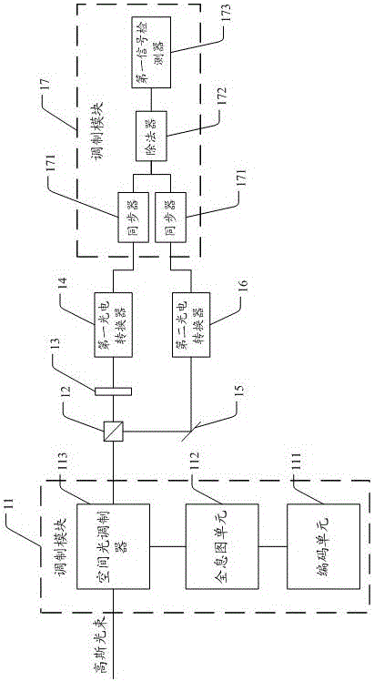
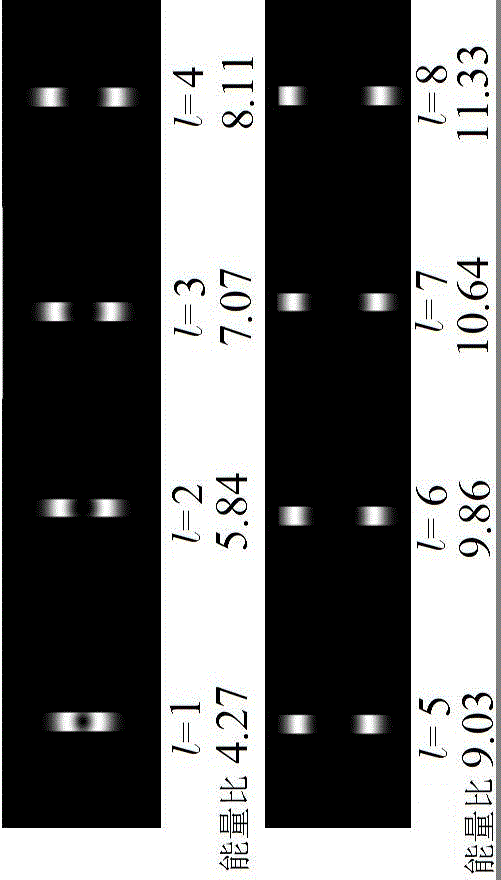
[0006] In view of the deficiencies of the above-mentioned prior art, the object of the present invention is to provide an optical orbital angular momentum signal demodulation device and method, by dividing the light beam into two parts and making one of the light beams pass through a slit filter, and detect the energy ratio of the two light beams The corresponding orbital angular momentum signal can be demodulated, which can solve the problems of complex structure, low efficiency and low speed of the existing OAM demodulation device

Method used


Image

  • Optical orbital angular momentum signal demodulation device and method
  • Optical orbital angular momentum signal demodulation device and method
  • Optical orbital angular momentum signal demodulation device and method

Examples


Embodiment Construction

[0058] In view of the shortcomings of the OAM demodulation device in the prior art, such as complex structure, low efficiency, and low rate, the object of the present invention is to provide an optical orbital angular momentum signal demodulation device and method, by using a slit of light and without slit The energy ratio of light from the slit can directly demodulate the orbital angular momentum signal, which has the advantages of simplicity and high efficiency.

[0059] In order to make the object, technical solution and effect of the present invention more clear and definite, the present invention will be further described in detail below with reference to the accompanying drawings and examples. It should be understood that the specific embodiments described here are only used to explain the present invention, not to limit the present invention.

[0060] see figure 1 The optical orbital angular momentum signal demodulation device provided by the first embodiment of the pr...


PUM


Abstract

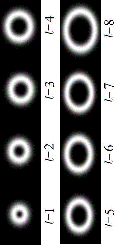
The invention discloses an optical orbital angular momentum signal demodulation device and method. The optical orbital angular momentum signal demodulation device comprises a modulation module, a beam splitter, a slit, a first photoelectric converter, a reflector, a second photoelectric converter and a demodulation module which are sequentially arranged along an optical path transmission direction; the modulation module generates N orbital angular momentum modulated beams in a vortex state; the orbital angular momentum modulated beams are divided into a first beam and a second beam by the beam splitter; after being filtered by the slit, the first beam is converted into a first electric signal by the first photoelectric converter; after being reflected by the reflector, the second beam is converted into a second electric signal by the second photoelectric converter; the demodulation module obtains an energy ratio of the first beam and the second beam according to the first electric signal and the second electric signal, and demodulates out a corresponding orbital angular momentum signal; by using the energy ratio of the light passing through the slit and the light which does not pass through the slit, the orbital angular momentum signal can be directly demodulated; and the optical orbital angular momentum signal demodulation device and method have the advantages of simplicity and high efficiency.

Description

technical field [0001] The invention relates to the technical field of optical communication, in particular to an optical orbital angular momentum signal demodulation device and method. Background technique [0002] In recent years, with the rapid development of services such as cloud computing, big data, and virtual reality, the demand for global network traffic and bandwidth has shown an exponential growth trend. With the gradual commercialization of communication technologies such as wavelength division multiplexing (WDM) and orthogonal frequency division multiplexing (OFDM), the traditional modulation / demodulation method has achieved a rapid increase in communication rate, but in essence, the traditional modulation / demodulation The modulation method is designed based on amplitude, frequency, phase and polarization state, which cannot get rid of the limitation of traditional dimensions and realize the doubling of communication capacity. Orbital Angular Momentum (OAM) com...

Claims


Application Information

Patent Timeline
IPC IPC(8): H04B10/516H04B10/67
CPCH04B10/516H04B10/67
Inventor 陈书青张小科贺炎亮蔡瑶唐进李瑛范滇元
Owner SHENZHEN UNIV
Why Eureka
Eureka Blog
Learn More