
Liquid nitrogen filling machine

A filling machine, liquid nitrogen technology, applied in mechanical equipment, gas/liquid distribution and storage, ship construction details, etc., can solve the problem that the floating ball cannot guarantee strict blocking of the column spacer, the pressure sensor cannot accurately transmit, and cannot be eliminated. temperature error and other problems, to achieve the effect of eliminating the influence of temperature, eliminating errors and ensuring stability

Active Publication Date: 2017-03-15
CHENGDU CRYOSTECH EQUIP CO LTD
View PDF6 Cites 1 Cited by
  • Summary
  • Abstract
  • Description
  • Claims
  • Application Information

AI Technical Summary

Problems solved by technology

However, due to the low temperature of liquid nitrogen, the floating ball is easy to freeze, and the frozen floating ball cannot guarantee to strictly seal the middle hole of the column spacer, so the pressure sensor cannot accurately transmit the information of stopping the continuous delivery of liquid nitrogen
Moreover, the pressure sensor has temperature hysteresis, which cannot eliminate the influence of temperature error, and the accuracy of the measured pressure value is low

Method used


Image

  • Liquid nitrogen filling machine

Examples


Embodiment Construction

[0017] Below in conjunction with accompanying drawing and embodiment the present invention is described further as follows:

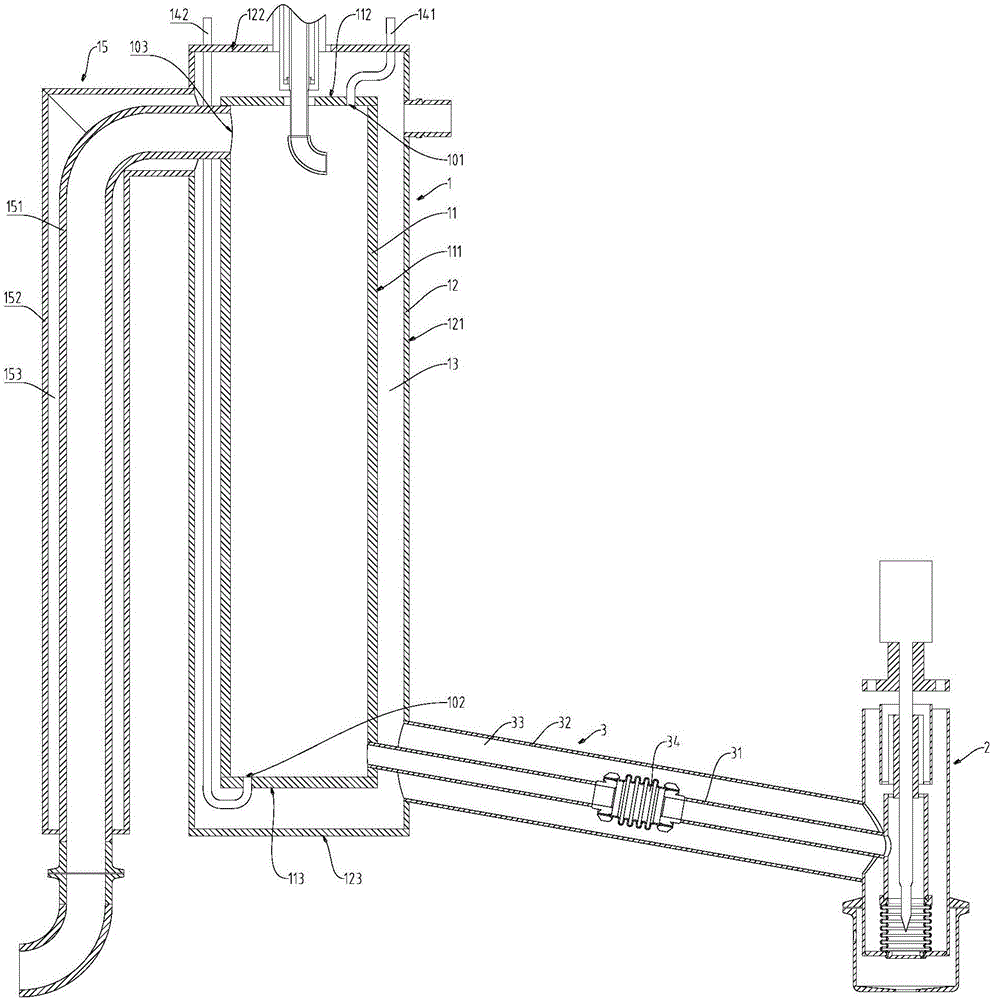
[0018] liquid nitrogen filling machine, such as figure 1 As shown, it includes heat preservation storage cylinder 1, heat preservation filling head 2 and heat preservation infusion tube 3; The end is provided with the bottom installation hole 102 extending to the inner cavity of the heat preservation storage cylinder 1; it includes a first pressure introduction pipe 141 and a second pressure introduction pipe 142; one end of the first pressure introduction pipe 141 is installed in the top installation hole 101, and the other One end extends above the thermal insulation storage cylinder 1 ; one end of the second pressure introduction pipe 142 is installed in the bottom mounting hole 102 , and the other end extends above the thermal insulation storage cylinder 1 .

[0019] In this liquid nitrogen filling machine, the thermal insulation storage cylinder 1...


PUM


Abstract

The invention provides a liquid nitrogen filling machine and belongs to the field of auxiliary devices for food packaging. In order to be beneficial to stable control of the liquid nitrogen filling pressure, the liquid nitrogen filling machine is provided. The liquid nitrogen filling machine comprises a heat-preserving storage cylinder, a heat-preserving filling head and a heat-preserving liquid conveying pipe, and further comprises a first pressure leading pipe and a second pressure leading pipe, wherein a top-end mounting hole which extends into the inner cavity of the heat-preserving storage cylinder is formed in the top end of the heat-preserving storage cylinder; a bottom-end mounting hole which extends into the inner cavity of the heat-preserving storage cylinder is formed in the bottom end of the heat-preserving storage cylinder; one end of the first pressure leading pipe is mounted at the top-end mounting hole; the other end of the first pressure leading pipe extends to a position I above the heat-preserving storage cylinder; one end of the second pressure leading pipe is mounted at the bottom-end mounting hole; and the other end of the second pressure leading pipe extends to a position II above the heat-preserving storage cylinder. By adoption of the liquid nitrogen filling machine, errors caused by temperature hysteresis and a floating ball can be eliminated, the measure pressure value precision can be improved, and the liquid nitrogen filling pressure and the height of a liquid level can be correctly controlled, thereby guaranteeing the liquid nitrogen filling stability.

Description

technical field [0001] The invention belongs to the technical field of food packaging auxiliary devices, in particular to a liquid nitrogen filling machine. Background technique [0002] Liquid nitrogen filling is widely used in food canning and other fields. Liquid nitrogen filling machine is an important equipment for liquid nitrogen filling, which directly affects the efficiency of liquid nitrogen filling. The Chinese invention patent application with the application number 201320725102.0 discloses a liquid nitrogen filling machine, which has a compact structure and good quality of the pure liquid phase of liquid nitrogen. In this liquid nitrogen filling machine, the floating ball floats with the liquid surface of the liquid nitrogen in the heat preservation storage cylinder. When the floating ball seals the middle hole of the spacer and the pressure of the liquid nitrogen above the spacer reaches the set value, the pressure sensor sends out a signal. The control stops t...

Claims


Application Information

Patent Timeline
IPC IPC(8): F17C7/02F17C13/00F17C13/02F17C13/10
CPCF17C7/02F17C13/00F17C13/025F17C13/10F17C2201/0104F17C2203/0391F17C2221/014F17C2223/013
Inventor 廖春平谭启忠
Owner CHENGDU CRYOSTECH EQUIP CO LTD
Learn More