Valve disk

A technology of valve disc and valve body, which is applied in the direction of lifting valve, valve device, engine components, etc., can solve the problems of large flow resistance and eddy current, and achieve the effect of reducing eddy current

Active Publication Date: 2017-03-15
VAG ARMATUREN
View PDF5 Cites 2 Cited by
  • Summary
  • Abstract
  • Description
  • Claims
  • Application Information

AI Technical Summary

Problems solved by technology

However, the stronger (thicker) the size of the valve disc is designed, the greater the flow resistance of the valve disc to the medium.
[0003] In the previously known valve disks with two opposing hubs, the problem also arises that, depending on the shape and width of the hubs, the hubs in the flow can generate swirl regions which are located on the discharge side. eddies in the flow area

Method used


Image

  • Valve disk
  • Valve disk
  • Valve disk

Examples


Embodiment Construction

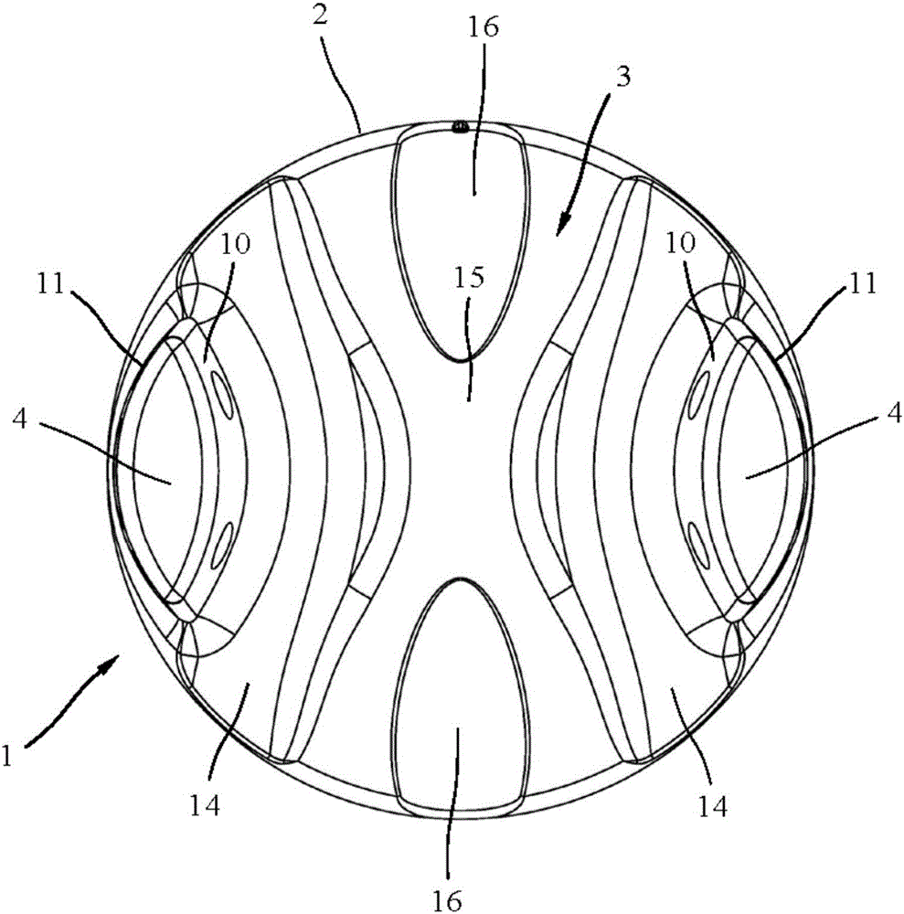
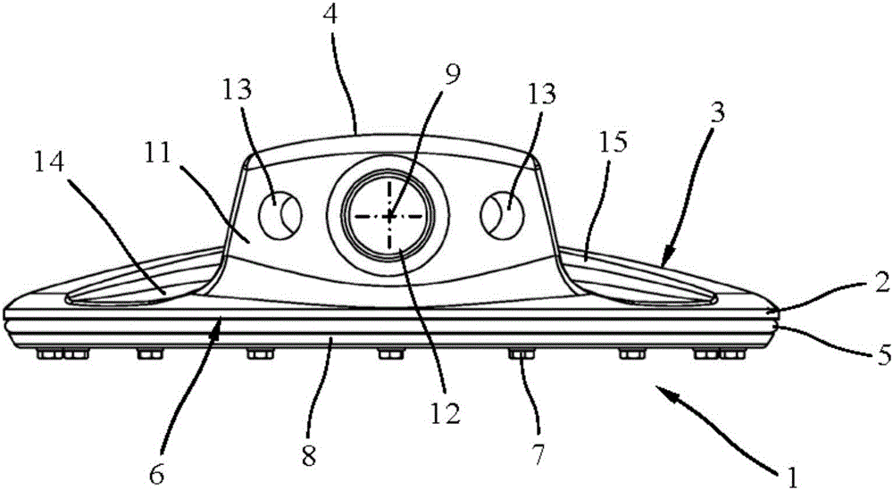
[0020] exist figure 1 top view of and figure 2 The valve disc 1 of the shut-off valve is shown in the side view. The valve disk 1 shown comprises a disk-shaped valve body part 2 which has on its outer side two hubs 4 protruding relative to the front side 3 of the valve body part 2 and facing each other. The valve disc 1 is also included in the figure 2 An annular or disk-shaped seal 5, which can be seen in the figure, and a fastening ring 8 releasably fastened on the back side 6 of the valve body 2 by means of a screw 7, by which the seal 5 is tightly Fixed on the valve body part 2. The valve body 2 of the valve disk 1 is mounted in a known manner in a housing interior in which the circular through-opening is provided so as to be pivotable about a rotational axis 9 extending perpendicularly to the central axis of the through-opening.

[0021] Such as figure 1 It is known that the valve body 2 has, on its front side 3 arranged between the hubs 4 , a contour which will be...


PUM


Abstract

The invention discloses a valve disk 1 with a disk-like valve body 2, which has a front 3 with two protruding hubs 4 and a back 6 opposite the front 3. In order to permit improved flow around the valve disk and reduction of eddies on the outflow side, arc-like recesses running along an inside surface 10 of both hubs 4 are arranged on the front 3 of valve body 2 to deflect the flow around hubs 4.

Description

technical field [0001] The invention relates to a valve disk for a shut-off valve according to the preamble of claim 1 . Background technique [0002] Globe valves are widely used cut-off mechanisms in water resource management systems. Compared with shut-off valves, shut-off valves are very compact and require considerably less construction space, especially with nominal inner diameters larger than DN 300. Pipeline systems with nominal inner diameters from about DN300 are therefore usually equipped with shut-off valves. On the other hand, a shut-off valve has the disadvantage that the valve disk, which is rotatably mounted inside the housing, is situated directly in the flow. Since the valve disk has to withstand system pressure differences in the closed position, the valve disk must be designed correspondingly thick especially for high pressure differences. However, the stronger (thicker) the size of the valve disc is designed, the greater the flow resistance that the v...

Claims


Application Information

Patent Timeline
Patent Type & Authority Applications(China)
IPC IPC(8): F16K1/20F16K1/36
CPCF16K1/222F16K1/36F16K1/2014F16K1/2028
Inventor P·蒂森T·F·鲁普H·E·赫罗尔德C·舒尔茨
Owner VAG ARMATUREN
Why Eureka
Try Eureka