A flapping-wing aircraft capable of vertical take-off and landing and its flight control method

A flapping-wing aircraft and vertical take-off and landing technology, applied in the field of aircraft, can solve problems such as the inability to meet the requirements of large lift, difficulty in increasing the flapping frequency, and small lift of flexible blades, and achieve compact structure, high flapping frequency, flapping wings, etc. Mechanism Simple Effect

Active Publication Date: 2018-09-21
NANJING UNIV OF AERONAUTICS & ASTRONAUTICS
View PDF6 Cites 0 Cited by
  • Summary
  • Abstract
  • Description
  • Claims
  • Application Information

AI Technical Summary

Problems solved by technology

[0004] 1. The control of pitch, roll, and yaw is accomplished only by flapping two blades. The flapping mechanism is complicated, the flapping frequency is difficult to increase, the lift is small, and the efficiency is not high.
[0005] 2. Since the root of the blade of the existing flapping wing mechanism does not have a hinge that can change the angle of attack of the blade, the existing flapping wing mechanism can only use flexible blades, relying on the deformation of the blade itself to change the angle of attack, the lift that the flexible blade can generate is small , unable to meet the requirements of large lift

Method used


Image

  • A flapping-wing aircraft capable of vertical take-off and landing and its flight control method
  • A flapping-wing aircraft capable of vertical take-off and landing and its flight control method
  • A flapping-wing aircraft capable of vertical take-off and landing and its flight control method

Examples


Embodiment Construction

[0024] The present invention will be further described below in conjunction with accompanying drawing.

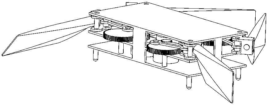
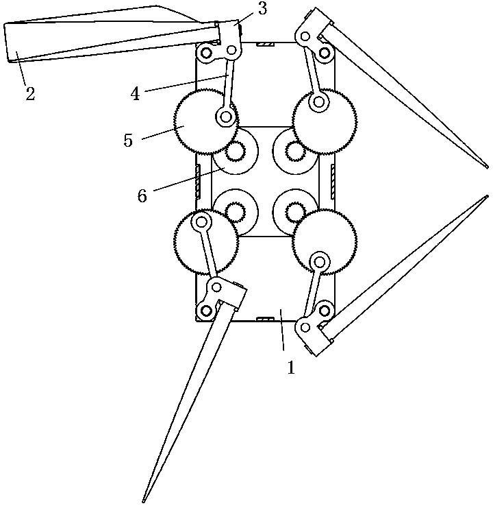
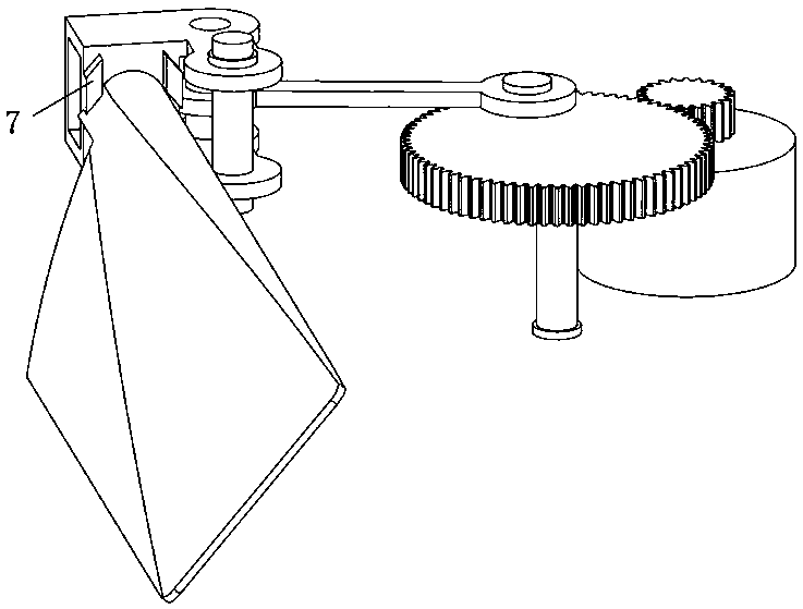
[0025] The invention provides a vertical take-off and landing flapping wing aircraft, such as figure 1 , figure 2 As shown, it includes the main load-bearing structure 1 of the fuselage and four sets of independent flapping wing mechanisms with the same structure. The main load-bearing structure 1 of the fuselage has a landing gear below. When the aircraft is placed on a horizontal plane, The bottom surface of the main bearing structure 1 of the fuselage is parallel to the horizontal plane. Described four sets of flapping wing mechanisms are distributed on the four corners of the main load-bearing structure 1 of the fuselage, and each set of flapping wing mechanisms is as follows: image 3 Shown, all comprise blade 2, rocking bar 3, connecting rod 4, crank 5 and motor 6. The blade 2 is as Figure 5 As shown, the first hinge is connected to the rocker 3, and the axis of...


PUM


Abstract

The invention provides a vertical taking-off and landing ornithopter and a flight control method thereof. The vertical taking-off and landing ornithopter comprises a main load-carrying structure of the ornithopter body and four independent flapping wing mechanisms having the same structures. The four independent flapping wing mechanisms are distributed in the four corners of the main load-carrying structure of the ornithopter body. Each one of the flapping wing mechanisms comprises blades, a rocker, a link, a crank and a motor. The blades are connected to the rocker through a first hinge. The rocker is connected to the main load-carrying structure of the ornithopter body through a second hinge. The rocker is connected to the link through a third hinge. The link is connected to the crank through a fourth hinge. The crank is driven by the motor with a driving gear. The axis of a motor output shaft is perpendicular to the bottom surface of the main load-carrying structure of the ornithopter body. A base of the motor is fixed on the main load-carrying structure of the ornithopter body. The crank, the link, the rocker and the main load-carrying structure of the ornithopter body form a crank-rocker mechanism. The vertical taking-off and landing ornithopter has a compact structure and allows use of highly rigid blades, the blade strength is easily guaranteed, a large lifting force is produced and the flight control method is simple.

Description

technical field [0001] The invention relates to the field of aircraft, in particular to a vertical take-off and landing flapping-wing aircraft and a flight control method thereof. Background technique [0002] In nature, the flapping-wing flight of some birds and insects can achieve rapid take-off, acceleration and hovering, with high maneuverability and low energy consumption. Due to the vertical take-off and landing capability of the flapping-wing aircraft, It has more advantages in a small space, and has very broad application prospects in military and civilian applications. The United States has developed the "Hummingbird" miniature flapping-wing aircraft, which has made breakthroughs in vertical take-off and landing, forward and backward. [0003] In the prior art, the vertical take-off and landing flapping wing aircraft has the following problems: [0004] 1. The control of pitch, roll and yaw is accomplished only by flapping the two blades. The flapping mechanism is...

Claims


Application Information

Patent Timeline
Patent Type & Authority Patents(China)
IPC IPC(8): B64C33/02
CPCB64C33/02
Inventor 冯卓群郑祥明刘媛媛徐哲蒋进
Owner NANJING UNIV OF AERONAUTICS & ASTRONAUTICS
Why Eureka
Try Eureka