
Headlamp device for a motor vehicle

A technology for vehicles and headlights, applied in lighting devices, signal devices, headlights, etc., can solve problems such as adverse effects on driving comfort, and achieve improved light quality and light intensity, high driving comfort, and fine spatial resolution Effect

Inactive Publication Date: 2017-03-15
GM GLOBAL TECH OPERATIONS LLC
View PDF6 Cites 6 Cited by
  • Summary
  • Abstract
  • Description
  • Claims
  • Application Information

AI Technical Summary

Problems solved by technology

Furthermore, this section of the high-beam distribution is considered to be a rasterization of disturbances in the high-beam distribution from the perspective of the driver, which also has a negative effect on driving comfort.

Method used


Image

  • Headlamp device for a motor vehicle
  • Headlamp device for a motor vehicle
  • Headlamp device for a motor vehicle

Examples


Embodiment Construction

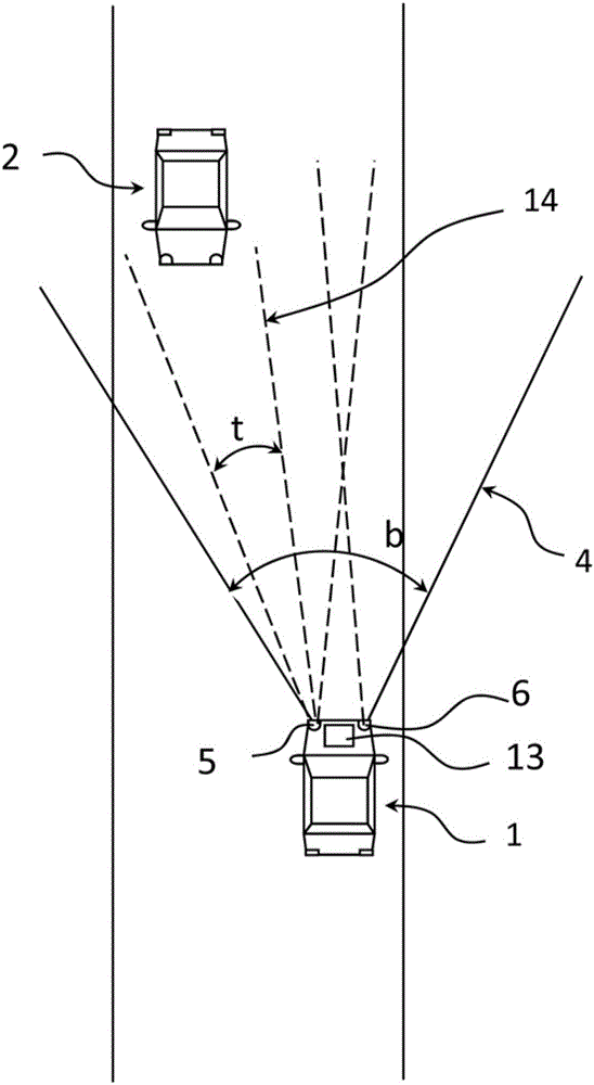
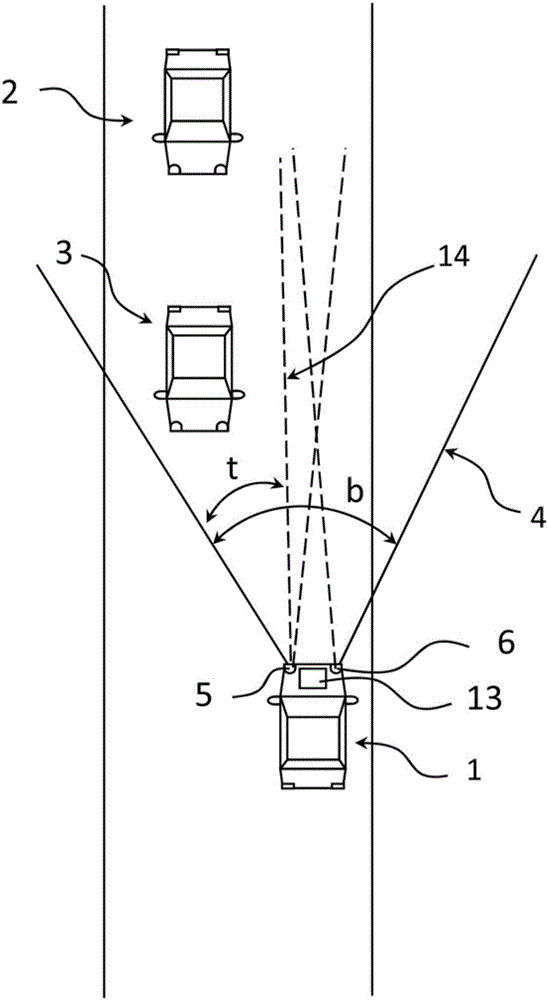
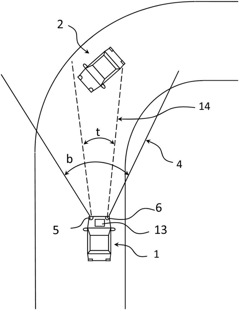
[0068] figure 1 A first driving situation on a straight road is shown schematically to explain the invention. Shown are a vehicle 1 traveling on a straight road section and a vehicle 2 traveling in the opposite direction to the direction of travel of the vehicle 1 . The vehicle 1 has a left headlight 5 and a right headlight 6 .

[0069] In this exemplary embodiment, the headlights 5 and 6 of the vehicle 1 are LED matrix headlights with individually controllable matrix segments. Headlamps 5 and 6 have the figure 1 The high beam distribution shown by light cone 4 in the middle. The light cone 4 of the high beam emitted by the LED matrix headlights of the vehicle 1 is schematically represented by two solid lines with an opening angle b. The opening angle b here corresponds to the full maximum high beam width of the headlights 5 and 6 .

[0070] The vehicle 1 has an environment sensor in its front area, which is designed as a camera 13 , for detecting the environment. Furthe...


PUM


Abstract

The invention discloses a headlamp device for a motor vehicle. The headlamp includes a segmented light source, which has individually deactivatable light source segments for generating a glare-free main beam with the aid of an automatic dimming system. The headlamp device is configured such that one or more regions in the main beam distribution of the headlamp device can be suppressed selectively by deactivating individual light source segments. Each light source segment in the activated state lights up a main beam segment region (L1-L8, R1-R8) with a respectively preset width in the main beam distribution of the headlamp. The width of the main beam segment region (L1-L8, R1-R8) is preset in the main beam segment region (L1-L8, R1-R8) depending on an expected average dynamic of objects to avoid dazzling under normal traffic conditions.

Description

technical field [0001] The invention relates to a headlight device of a vehicle or a vehicle. Background technique [0002] The headlight system of a vehicle comprises an increasing number of headlight devices which can be controlled by a special controller in order to ensure that on the one hand the driver of the vehicle can recognize the path to be driven and related objects as far in advance as possible, and on the other hand Avoid being dazzled by other traffic participants. The automatic anti-dazzle system suppresses the high beams in a targeted manner in the area of ​​the high beam distribution, thereby protecting road users from being dazzled. [0003] The occlusion of a specific area of ​​high beam distribution by an automatic device is usually referred to as GFHB (Glare-Free-High-Beam), GFHB automatic device or ADB (Adaptive Driving Beam (Adaptive Driving Beam)) known. [0004] Headlight systems are known in which road users are dazzled by means of mechanically m...

Claims


Application Information

Patent Timeline
IPC IPC(8): B60Q1/08H05B44/00
CPCB60Q1/08B60Q2300/056H05B45/10H05B47/105H05B47/125B60Q1/1423B60Q1/16B60Q2300/42
Inventor J.伊利尤姆T.费德R.哈伯肯I.施耐德M.邦
Owner GM GLOBAL TECH OPERATIONS LLC
Learn More