
Cleaning flexible shaft and pipeline cleaning system and method

A cleaning system and flexible shaft technology, applied in cleaning methods and utensils, chemical instruments and methods, and smoke and dust removal, etc., can solve the problems of low cleaning efficiency and single function of air-conditioning pipes, and achieve the goal of reducing air pressure impulse and slowing inhalation rate. Effect

Active Publication Date: 2017-03-15
广东齐创科技投资集团有限公司
View PDF12 Cites 11 Cited by
  • Summary
  • Abstract
  • Description
  • Claims
  • Application Information

AI Technical Summary

Problems solved by technology

[0002] At present, the equipment used to clean air-conditioning pipes on the market mainly includes flexible shaft cleaning machines, vacuum cleaners and cleaning robots. However, the flexible shaft cleaning machines, vacuum cleaners and cleaning robots are separate and independent of each other, and each device has a single function , when cleaning the air-conditioning pipes, it is necessary to use various equipment together to achieve a better cleaning effect, which brings great inconvenience to the cleaning staff of the air-conditioning pipes. When cleaning the air-conditioning pipes, the staff need to At the same time, because each device has a single function, the cleaning efficiency of the air-conditioning pipe cleaning staff is low

Method used


Image

  • Cleaning flexible shaft and pipeline cleaning system and method
  • Cleaning flexible shaft and pipeline cleaning system and method
  • Cleaning flexible shaft and pipeline cleaning system and method

Examples


Embodiment Construction

[0047] Embodiments of the present invention will be described in detail below.

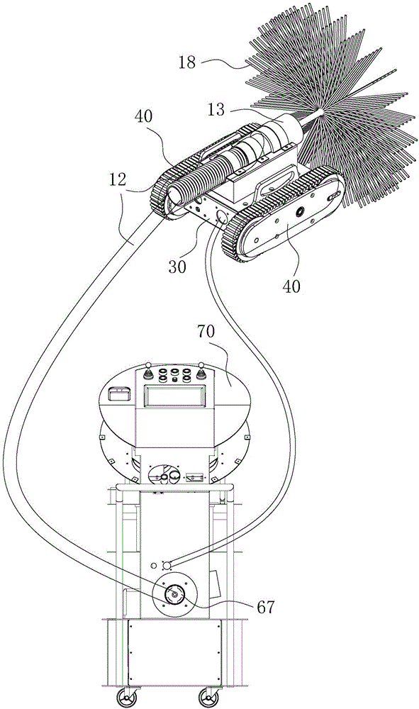
[0048] Such as Figure 1 to Figure 11 As shown, the pipeline cleaning system includes a seat body 30, a traveling mechanism 40, a control terminal and a cleaning flexible shaft,

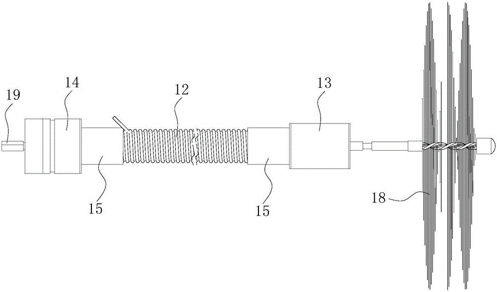
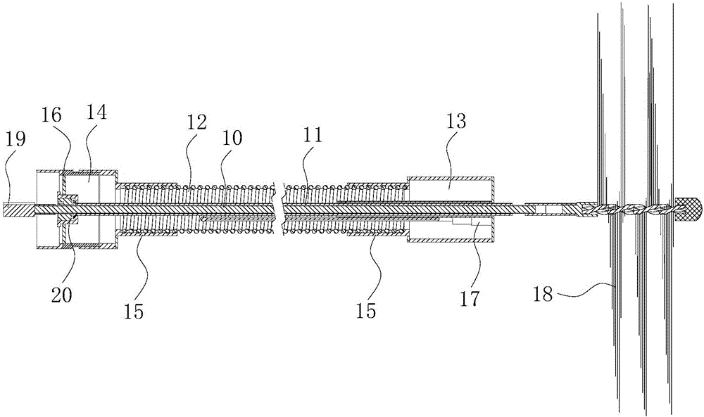
[0049] Clean the flexible shaft, including the flexible shaft shaft core 10, the shaft core sleeve 11, the ventilation pipe 12, the dust suction end piece 13 and the connecting piece 14, the shaft core sleeve 11 is sleeved on the flexible shaft shaft core 10; 12 sets of ventilation pipes Set on the shaft core sleeve 11, there is a gap between the ventilation pipe 12 and the shaft core sleeve 11 to form a ventilation channel; one end of the ventilation pipe 12 is connected to the dust suction end piece 13, and the other end is connected to the connector 14; The dust end piece 13 has a front panel 131, the front panel 131 is provided with a first ventilation hole, a support plate 16 is provided between the connecting piec...


PUM


Abstract

The invention discloses a cleaning flexible shaft and a pipeline cleaning system and method. The cleaning flexible shaft comprises a flexible shaft core, a shaft core sleeve, a ventilating pipe, a dust collection end piece and a connecting piece. The shaft core sleeve is arranged on the flexible shaft core in a sleeving mode. The ventilating pipe is arranged on the shaft core sleeve in a sleeving mode, and the ventilating pipe and the shaft core sleeve form a ventilating channel. The two ends of the ventilating pipe are connected with the dust collection end piece and the connecting piece correspondingly. The dust collection end piece is provided with a first ventilating hole. A second ventilating hole is formed in a supporting plate which is arranged between the connecting piece and the shaft core sleeve. The first ventilating hole, the ventilating channel and the second ventilating hole communicate with one another. The pipeline cleaning system comprises a base body, walking mechanisms, a control terminal and the cleaning flexible shaft. The walking mechanisms are arranged on the two sides of the base body. The cleaning flexible shaft is arranged on the base body. The control terminal is provided with a flexible shaft connecting part. The back end of the cleaning flexible shaft is connected with the flexible shaft connecting part. The cleaning flexible shaft and the pipeline cleaning system can be used for pipeline cleaning and also can collect dust during pipeline cleaning, using is convenient, and the pipeline cleaning efficiency can be improved.

Description

technical field [0001] The invention relates to the field of pipeline cleaning equipment, in particular to a cleaning flexible shaft, a pipeline cleaning system and a pipeline cleaning method. Background technique [0002] At present, the equipment used to clean air-conditioning pipes on the market mainly includes flexible shaft cleaning machines, vacuum cleaners and cleaning robots. However, the flexible shaft cleaning machines, vacuum cleaners and cleaning robots are separate and independent of each other, and each device has a single function , when cleaning the air-conditioning pipes, it is necessary to use various equipment together to achieve a better cleaning effect, which brings great inconvenience to the cleaning staff of the air-conditioning pipes. When cleaning the air-conditioning pipes, the staff need to Carry each equipment, and at the same time, because each equipment has a single function, the cleaning efficiency of the air-conditioning duct cleaning staff is...

Claims


Application Information

Patent Timeline
Patent Type & Authority Applications(China)
IPC IPC(8): B08B9/049B08B15/04
CPCB08B9/049B08B15/04
Inventor 尚方杰
Owner 广东齐创科技投资集团有限公司
Learn More