A solid-liquid separation device
A technology of solid-liquid separation and solid-liquid separator, which is applied in the direction of separation method, sedimentation separation, sediment separation by centrifugal force, etc., can solve the problems of multi-space and poor filtering effect, and achieve the goal of saving energy and promoting solid-liquid separation Effect
- Summary
- Abstract
- Description
- Claims
- Application Information
AI Technical Summary
Problems solved by technology
Method used
Image
Examples
Embodiment 1
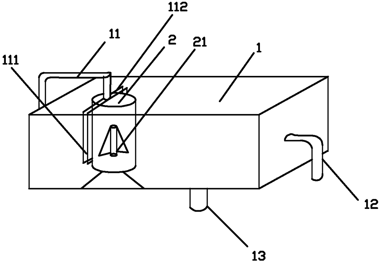
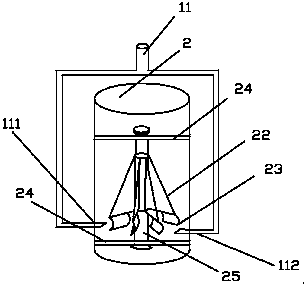
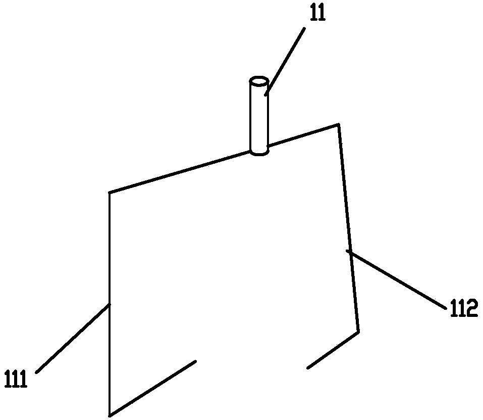
[0026] Such as Figure 1-4 As shown, a solid-liquid separation device includes a sedimentation tank 1, an inlet pipe 11 is arranged on one side of the sedimentation tank 1, and an outlet pipe 12 is arranged on the other side, and a sewage discharge pipe 13 is arranged on the bottom of the sedimentation tank 1. A solid-liquid separator 2 is provided below the water inlet pipe 11, and the water inlet pipe 11 is set as a three-way pipe, so that the incoming water flow will be divided into two water flows, and the bottom of the solid-liquid separator 2 is oppositely provided with a first water pipe 111 and the second water pipe 112, because the two are oppositely arranged, so when the water flows out from the two outlets, convection will be formed. The first and second water pipes are connected with the water inlet pipe, and the two are oppositely arranged. The centers of the first water pipe 111 and the second water pipe 112 are not on the same straight line, the two are not on t...
Embodiment 2
[0028] Such as Figure 1-2 As shown, the same parts of this embodiment and Embodiment 1 will not be repeated, and the difference is:
[0029] The sloping plate part 22 is set as a right-angled triangular plate, and the plate of this shape is more conducive to pushing and rotating by means of the gravity of water. The long right-angled side of the sloping plate part 22 is arranged outside the main shaft 25 and is parallel to the axis of the main shaft 25 , which is designed to allow the hypotenuse of the triangle to contact the water to form a thrust. The swirl part 23 is arranged below the short right-angled side of the swash plate part 22, so that when the water drives the swash plate part 22 to rotate, it drives The swirl part 23 rotates to form a vortex at the bottom to improve the efficiency of solid-liquid separation, and the width of the swirl part 23 is 1 / 4-1 / 2 of the short right-angled side. This design can meet the requirements of the solid-liquid separator. 2 The vo...
PUM
 Abstract
Description
Claims
Application Information
 - R&D
- Intellectual Property
- Life Sciences
- Materials
- Tech Scout
- Unparalleled Data Quality
- Higher Quality Content
- 60% Fewer Hallucinations
Browse by: Latest US Patents, China's latest patents, Technical Efficacy Thesaurus, Application Domain, Technology Topic, Popular Technical Reports.
© 2025 PatSnap. All rights reserved.Legal|Privacy policy|Modern Slavery Act Transparency Statement|Sitemap|About US| Contact US: help@patsnap.com


