
Electric power circuit stringing device across river

A technology for power lines and rivers, applied in the direction of overhead lines/cable equipment, etc., can solve problems such as damage from crossing the bridge, stagnation of power lines, affecting the construction process, etc., to ensure stability, ease of erection, and ease of transportation.

Inactive Publication Date: 2017-03-08
NANYANG POWER SUPPLY COMPANY OF STATE GRID HENAN ELECTRIC POWER
View PDF8 Cites 7 Cited by
  • Summary
  • Abstract
  • Description
  • Claims
  • Application Information

AI Technical Summary

Problems solved by technology

Since the power line that needs to be erected or dismantled is pulled by the trolley, it needs to move between two adjacent iron towers, and in the process of moving the power line, it is supported by the spanning frame and slides on it, thus It can be seen that the spanning frame not only bears the weight of the power line, but also produces sliding friction with the power line. Therefore, no matter how strong the spanning frame is, it is easily worn by the large friction force generated by the sliding power line, especially The disassembled old power line, because of its surface similar to the sawtooth-shaped tip, is more likely to damage the spanning frame; in addition, the frictional resistance between the power line and the spanning frame will also have a greater impact on the traction components, due to the The guide rope and the pulley, as well as the pulley are affected by the wind force in the high altitude, and the guide rope and the stay wire are often entangled and the pulley is offset. After this phenomenon occurs, it is difficult for the pulley to move. In the offset state, it is necessary to overcome the frictional resistance between the power line and the spanning frame to move the power line, which will easily cause the stagnation of the power line and other phenomena, which will affect the construction process and increase the amount of maintenance. The construction cost will increase significantly
In the Chinese patent with application number 201310373308.6, an overhead line cross-laying device is disclosed, including an overhead suspension wire, a pay-off vehicle, a traction block with a driving mechanism, and a suspension wire pulley. The front end of the overhead suspension wire passes through a tensioning mechanism Connected to the fixed object in front of the spanning object, the traction block pulls the wire to be laid to move on the elevated suspension line, the suspended wire supporting wheel supports the wire and hangs on the elevated suspension wire, and the wire outlet end of the pay-off vehicle is set Wire anti-twisting device, the lower part of the traction block is equipped with a counterweight balancer; although this invention can solve the problem of wire laying, it does not solve the technical problem of river crossing operations

Method used


Image

  • Electric power circuit stringing device across river
  • Electric power circuit stringing device across river
  • Electric power circuit stringing device across river

Examples


Embodiment 1

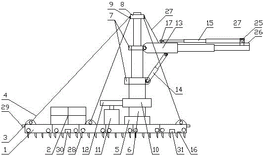
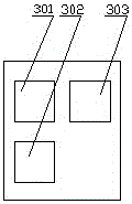
[0029] like figure 1 and figure 2 As shown, a power line stringing device across a river includes a ground anchor mechanism for enhancing stability, a support mechanism arranged on the ground anchor mechanism, and a spanning mechanism arranged on the support mechanism. The anchor mechanism, the support mechanism and the span mechanism are all connected to the control mechanism 16 .

[0030] The ground anchor mechanism includes a ground anchor plate 1 composed of a plurality of ground anchor units, a counterweight unit 2 arranged on the ground anchor plate 1, a load-bearing ring 3 arranged on the side of the ground anchor plate 1, and a load-bearing ring connected with the ground anchor plate 1. 3 connected pull ropes 4 .

[0031] The support mechanism includes a rotary base 5 that is rotated on the ground anchor plate 1, a telescopic rod 6 that is mounted on the rotary base 5, and a fixed seat 7 that is mounted on the telescopic rod 6. The telescopic rod 6 The upper end is...

Embodiment 2

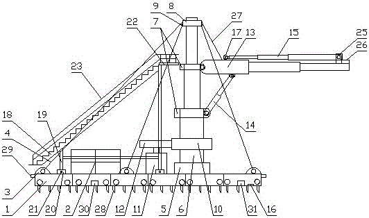
[0043] like image 3 As shown, the difference between it and the second embodiment is that a temporary freight elevator 18 is provided on the ground anchor mechanism, and a chute 20 is provided on the ground anchor plate 1 corresponding to the positions of the four legs 19 of the temporary freight elevator 18. The side of the chute 20 is provided with locking pins 21 for locking the four legs 19 of the temporary freight elevator 18, the temporary operating platform 22 is arranged on the top of the temporary freight elevator 18, and the two side edges of the temporary freight elevator 18 and the Safety fences 23 are all set around the temporary operating platform 22.

[0044] In this embodiment, in order for the construction personnel to easily climb the telescopic rod and the main telescopic arm for operation and maintenance, a temporary freight elevator is set on the ground anchor mechanism, and a temporary operating platform is set on the upper part of the temporary freight ...

Embodiment 3

[0046] like Figure 4 and Figure 5 As shown, the difference between it and Embodiment 2 is that an automatic wire feeding mechanism 24 is provided at the lower part of the main telescopic arm 13, and the automatic wire feeding mechanism 24 includes a bracket 241 arranged at the lower part of the main telescopic arm 13, which is rotatably arranged on The driving wheel set 242 at the inner lower part of the bracket 241, the driven wheel set 243 arranged on the upper inner side of the bracket 241 and matched with the driving wheel set 242, and the output motor arranged at the upper left side of the bracket 241 244, the output motor 244 is electrically connected to the control mechanism 16, the output end of the output motor 244 is connected to the rotating shaft of the driving wheel set 242, and the driving wheel set 242 is connected to the driven wheel set 243 to form a gap for transmitting electric power lines.

[0047] In this embodiment, an automatic wire transmission mech...


PUM


Abstract

The invention discloses an electric power circuit stringing device across a river. The stringing device comprises a ground anchor mechanism used for improving stability, a support mechanism arranged on the ground anchor mechanism and an across mechanism arranged on the support mechanism. The ground anchor mechanism, the support mechanism and the across mechanism are connected with a control mechanism. The support mechanism comprises a revolving base rotatably arranged on a ground anchor plate, a telescoping rod arranged on the revolving base and a fixed seat arranged on the telescoping rod. A sleeve ring is rotatably arranged on the upper end of the telescoping rod. The outer surface of the sleeve ring is equipped with a fixed ring connected with a traction rope. A big gear wheel is fixedly arranged on the lower part of the telescoping rod. A driving motor is arranged on the ground anchor plate. A small gear wheel engaged with the big gear wheel is arranged on the output shaft of the driving motor. The driving motor is connected with the control mechanism through electrical signals. The stringing device is advantageous in that the stringing device is simple to operate, easy to recycle, safe to operate and less affected by weather.

Description

technical field [0001] The invention belongs to the technical field of electric power construction auxiliary equipment, and in particular relates to a power line stringing device across a river. Background technique [0002] Since the quality of the transmission wire, especially the high-voltage transmission wire itself, is large, and the two adjacent iron towers used to support the transmission wire have a large span, and there are charged objects, crops, trees, etc. between the two adjacent iron towers. Obstacles such as rivers, roads, buildings and structures are crossed, so erecting or dismantling transmission lines is a complex and difficult project. [0003] In the prior art, erecting or dismantling power lines usually adopts a guide rope installed between two adjacent iron towers and a pulley suspended on the guide rope and controlled by a stay wire, and in order to prevent the power line from being connected to the ground or to the above-mentioned The spanning frame...

Claims


Application Information

Patent Timeline
Patent Type & Authority Applications(China)
IPC IPC(8): H02G1/04
CPCH02G1/04
Inventor 时伟
Owner NANYANG POWER SUPPLY COMPANY OF STATE GRID HENAN ELECTRIC POWER
Learn More