
Electronic product vibration DLP method based on cross-power spectrum function mode parameter identification

A technology of modal parameter identification and cross-power spectrum, which is applied in measuring devices, instruments, and measuring ultrasonic/sonic/infrasonic waves, etc.

Active Publication Date: 2017-03-08
BEIHANG UNIV
View PDF7 Cites 27 Cited by
  • Summary
  • Abstract
  • Description
  • Claims
  • Application Information

AI Technical Summary

Problems solved by technology

It overcomes the problem that the life prediction model parameters in the PHM method of electronic products under vibration conditions must be analyzed through finite element modal analysis, and cannot be obtained in real time by using online monitoring data, so that the remaining life prediction results are closer to the actual use of the product. The reliability analysis based on this is more scientific and reasonable, and the result is closer to the real level of the product

Method used


Image

  • Electronic product vibration DLP method based on cross-power spectrum function mode parameter identification
  • Electronic product vibration DLP method based on cross-power spectrum function mode parameter identification
  • Electronic product vibration DLP method based on cross-power spectrum function mode parameter identification

Examples


Embodiment Construction

[0091] Exemplary embodiments, features, and aspects of the present invention will be described in detail below with reference to the accompanying drawings. The same reference numbers in the figures indicate functionally identical or similar elements. While various aspects of the embodiments are shown in drawings, the drawings are not necessarily drawn to scale unless specifically indicated.

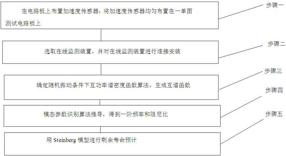
[0092] combine figure 1 The flow chart, the following embodiments include determining the cross power spectral density function algorithm under random vibration conditions, deriving the modal parameter identification algorithm, using the Steinberg model to predict the remaining life of circuit board components, selecting and testing electronic products and online monitoring devices, and generating cross power For the spectral density curve, the first-order resonance frequency and damping ratio are calculated according to the modal parameter identification algorithm and the cross-power sp...


PUM


Abstract

The invention provides an electronic product vibration DLP method based on cross-power spectrum function mode parameter identification. The method comprises the following steps of arranging acceleration sensors on a circuit board; uniformly arranging the acceleration sensors on a single-surface testing circuit board; selecting an online monitoring device, and performing connecting mounting on the online monitoring device; determining a cross-power spectrum function algorithm on a random vibration condition, and generating a cross-power spectrum density function; performing derivation of a mode parameter identification algorithm, and obtaining a first-order frequency and a damping ratio; and performing residual service life estimation by means of a Steinberg model. According to the electronic product vibration DLP method, finite-element analysis software such as vibration analysis software and simulation software are not required for simulating a vibration response mode. A vibration response data collecting operation can be finished just through the acceleration sensors and data collecting equipment. The electronic product vibration DLP method overcomes a defect that partial parameters of existing service life prediction software are empirical parameters which cannot be accurately calculated. Furthermore the first-order frequency and the damping ratio can be calculated through applying a mode identification method.

Description

technical field [0001] The invention belongs to the field of product fault prediction and health management, and provides a method for fault diagnosis and life prediction of electronic products in a vibration environment, in particular a vibration DLP method for electronic products based on the identification of modal parameters of a cross-power spectral density function. Background technique [0002] Electronic Product Failure Prediction and Health Management (PHM) integrates sensor model data that can assess the degradation of electronic products under normal operating conditions and evaluate the future reliability of products based on current and historical conditions. This technology has been gradually applied to the detection of high reliability field. In avionics and aerospace electronics systems, electronics are subject to many dynamic loads during normal operation, including high temperatures and temperature cycling, vibration and humidity. Data show that 20% of ele...

Claims


Application Information

Patent Timeline
Patent Type & Authority Applications(China)
IPC IPC(8): G01H17/00
CPCG01H17/00
Inventor 陈颖汤宁门卫阳
Owner BEIHANG UNIV
Learn More