
Driving tool

A technology of driving tools and driving tools, applied in nailing tools, manufacturing tools, etc., can solve the problems of compressed air blowing, easy peeling, difficult rubber, etc., and achieve the effect of increasing sliding resistance

Active Publication Date: 2017-03-08
MAX CO LTD
View PDF9 Cites 0 Cited by
  • Summary
  • Abstract
  • Description
  • Claims
  • Application Information

AI Technical Summary

Problems solved by technology

According to such a structure, even if the moisture in the compressed air freezes due to the adiabatic expansion of the compressed air, it is difficult to adhere to the elastic rubber with high adiabatic properties, and even if it adheres, it is easy to peel off, so it is easy to be blown away by the compressed air

Method used


Image

  • Driving tool
  • Driving tool
  • Driving tool

Examples


Embodiment Construction

[0029] The embodiments of the present invention will be described with reference to the drawings.

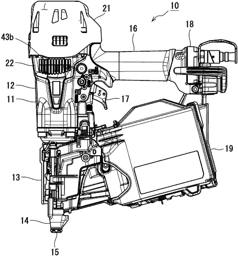
[0030] The driving tool 10 of this embodiment is a pneumatic driving tool 10 that uses compressed air to drive fasteners, such as figure 1 As shown, it is provided with: a tool body 11 with a machine head 13; and a silo 19 with the tool body 11 connected to it. A connecting fastener is stored in the bin 19, and the connecting fastener is drawn in the direction of the nose 13 and used.

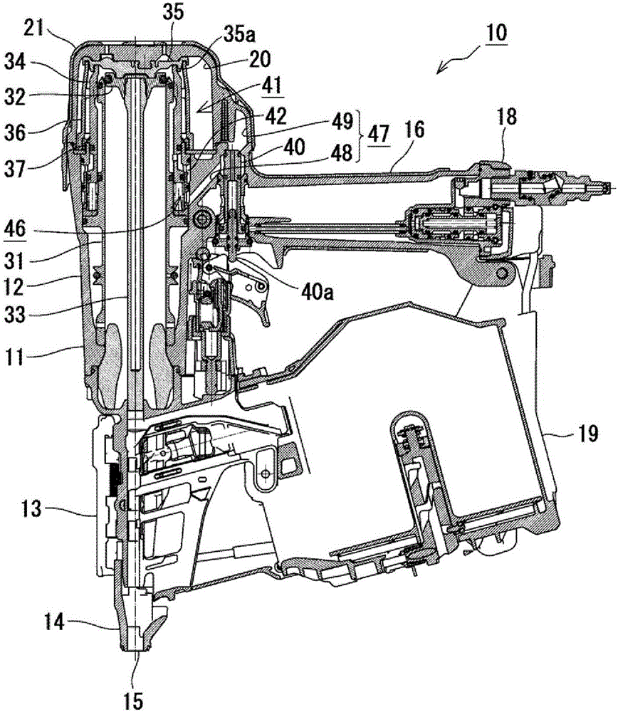
[0031] Such as figure 1 and figure 2 As shown, the tool body 11 includes: a body shell 12; a handle shell 16 which is connected to the body shell 12 substantially perpendicularly; and a head part 13, which is integrally fixed to the front end side of the body shell 12 (the direction in which fasteners are driven) ; And the cover housing 20, integrally fixed to the rear end side of the main body housing 12 (the direction opposite to the driving direction of the fastener).

[0032] Such as figure 2 As ...


PUM


Abstract

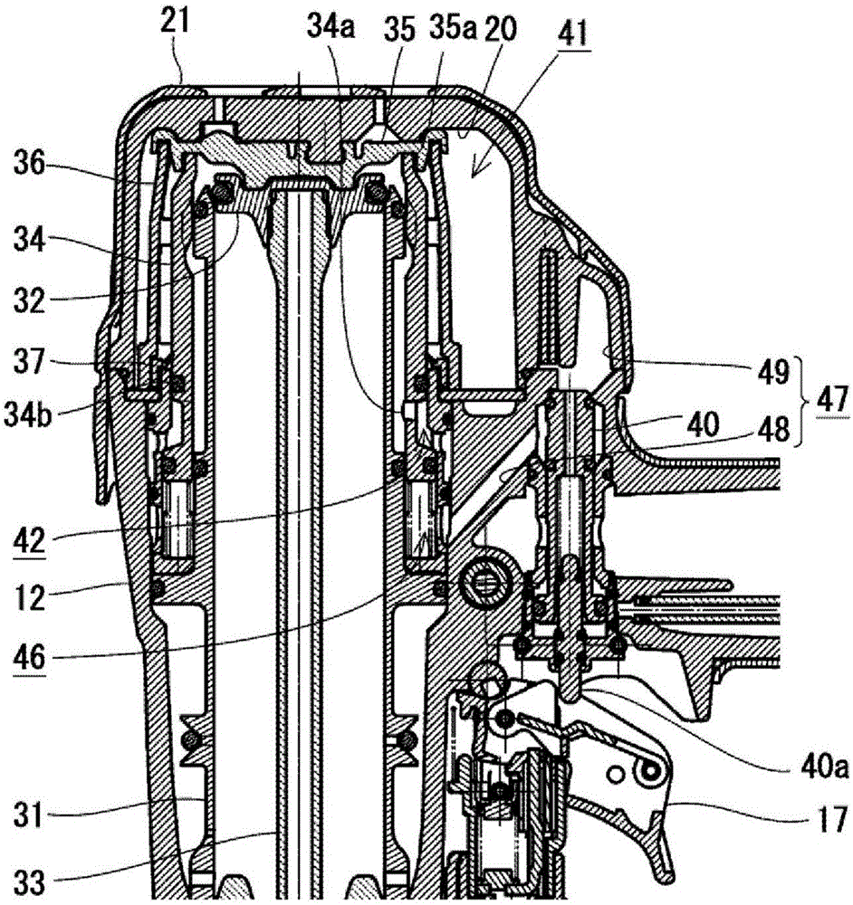
The present disclosure relates to a driving tool which operates a piston by compressed air to drive out a fastener, and particularly to a technology for preventing a foreign matter from entering an O-ring groove and the like of a head valve. The driving tool is provided with a foreign matter removing member (37) with a protruding portion (37c) facing a circumferential surface of a head valve (34). Therefore, a sealed port (34b) is covered by the foreign matter removing member (37), thereby preventing the foreign matter such as ice (50) from entering the sealed part (34b). When the head valve (34) slides to move relatively with respect to the foreign matter removing member (37), the protruding portion (37c) functions in a manner of erasing the circumferential surface of the head valve (34), and the ice (50) attached on the circumferential surface of the head valve (34) can be removed by the foreign matter removing member (37).

Description

Technical field [0001] The present invention relates to a driving tool for driving out fasteners by operating a piston by compressed air, in particular to a technique for preventing foreign matter from entering an O-ring groove of a top valve. Background technique [0002] This driving tool is equipped with a top valve that controls the inflow of compressed air into the cylinder. When the trigger of the driving tool is operated, the top valve slides. As a result, compressed air flows into the cylinder and the piston moves, thereby driving the fastener. [0003] However, during the nailing operation, the temperature around the top valve decreases due to the adiabatic expansion of the compressed air that has passed through the top valve. In particular, when the nailing operation is continuously performed in a low temperature and high humidity environment, the moisture contained in the compressed air may freeze due to a temperature drop caused by adiabatic expansion. When the ice pa...

Claims


Application Information

Patent Timeline
Patent Type & Authority Applications(China)
IPC IPC(8): B25C1/04
CPCB25C1/047B25C1/042
Inventor 关口则满田中宏司粟饭原泰宣足立道明
Owner MAX CO LTD
Learn More