Switched reluctance motor starting methods

An electric motor, reluctance motor technology, applied in the direction of a single reluctance motor starter, motor control, motor generator/starter, etc., can solve the problems of unacceptable, long duration of the first step, etc.

Inactive Publication Date: 2017-02-22
VALEO AIR MANAGEMENT UK
View PDF6 Cites 0 Cited by
  • Summary
  • Abstract
  • Description
  • Claims
  • Application Information

AI Technical Summary

Problems solved by technology

[0025] However, the known described methods above have the disadvantage that the duration of the first step may be unacceptably long

Method used


Image

  • Switched reluctance motor starting methods
  • Switched reluctance motor starting methods
  • Switched reluctance motor starting methods

Examples


Embodiment Construction

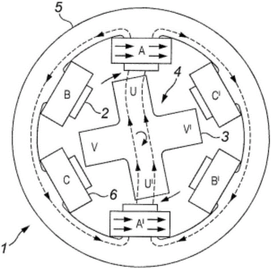
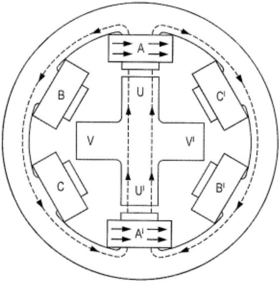
[0077] Figure 12 The flowchart of shows an example method of starting a switched reluctance motor as Figures 9 to 11 As shown, the stages of rotation of the switched reluctance motor are demonstrated. The motor in this example is similar to that of Figures 1 to 8, with six stator poles and four rotor poles (similarly labeled ABCA'B'C' and UVU'V'). (ABCA'B'C' likewise denote poles and individual coils of poles). It operates a motor control circuit similar to Figure 5 motor control circuit, except for the control circuit 10'( Figure 13 ) are arranged to control the switches 21 to 26 to turn on and off the coils of the motor as described in this example. In order to do this, a start-up controller 50 is provided (preferably implemented with additional programming in a microcontroller).

[0078] The rotor starts at any position, where the rotor may be stationary or slowly moving, such as Figure 9 as shown ( Figure 12 In step 101), all coils are turned off. In such a p...


PUM


Abstract

An improved method of starting a switched reluctance motor uses two neighbouring pairs of coils, both energised, to bring the rotor to its initial position. Then one of pairs of coils is turned off and the rotor is attracted by the other pair of coils to give it an initial rotational speed. An intermediate stage uses just one pair of coils of the motor to bring it up to operational speeds, after which the normal cycling of all the coils can be used.

Description

technical field [0001] The present invention relates to switched reluctance motors, and in particular to methods of starting such motors. Background technique [0002] exist Figure 1A , 1B and 2 to 4 show typical switched reluctance motors. This example has a combination of six, preferably evenly spaced poles 2 on the stator 1 and four, preferably evenly spaced poles 3 on the rotor 4 . In this example, the poles of the stator protrude inwardly from a stator ring 5 which provides a path for low reluctance material between the stator poles. [0003] The rotor is formed from a cross-shaped stack of laminations and is formed from a low reluctance material. Thus, for reasons that will become apparent, each rotor pole is connected to the diametrically opposed rotor pole by a low reluctance path. Thus, as marked, pole U is connected to pole U' by a low reluctance path, and pole V is connected to V' by a low reluctance path. [0004] Each pole of the stator is wound with a coi...

Claims


Application Information

Patent Timeline
Patent Type & Authority Applications(China)
IPC IPC(8): H02P1/46H02P25/08H02P1/16
CPCH02P1/163H02P1/46H02P25/0925H02P25/08H02P2203/05H02P6/17
Inventor 卡迈勒·布亚拉加多米尼克·杜普伊斯
Owner VALEO AIR MANAGEMENT UK
Why Eureka
Try Eureka