Power transmitting device, power receiving device, and wireless power supply system
A non-contact power supply and power receiving device technology, applied in the direction of circuit devices, battery circuit devices, control devices, etc., can solve the problem of power supply efficiency drop and achieve the effect of suppressing the cooling efficiency drop
- Summary
- Abstract
- Description
- Claims
- Application Information
AI Technical Summary
Problems solved by technology
Method used
Image
Examples
no. 1 approach
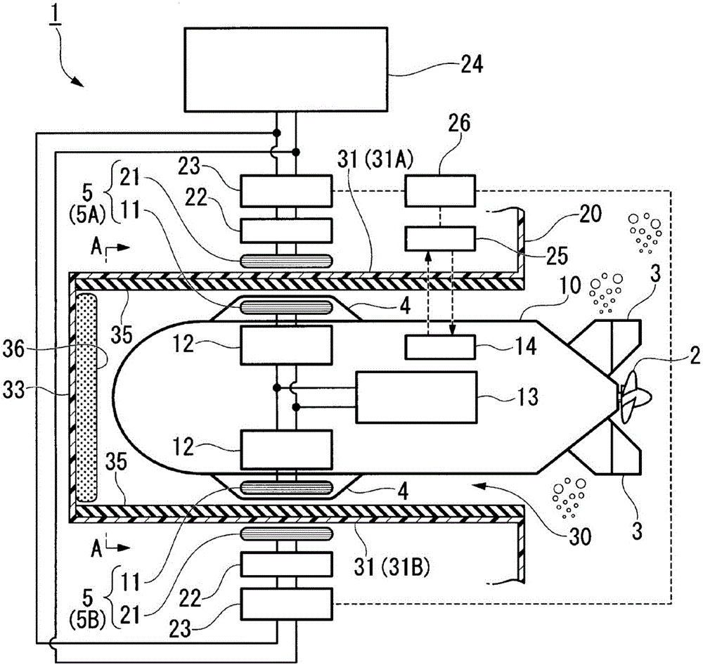
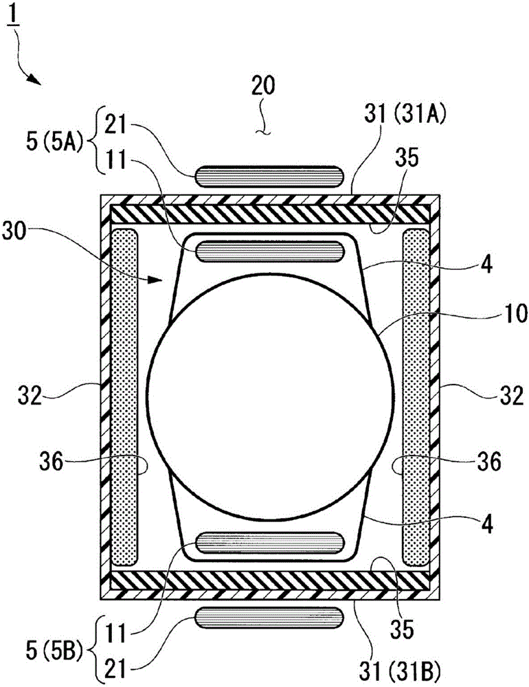
[0072] figure 1 It is an overall configuration diagram of the contactless power supply system 1 according to the first embodiment of the present invention. figure 2 yes figure 1 The A-A diagram of the direction of view.
[0073] The contactless power supply system 1 performs contactless power supply using a coil pair 5 between at least one movable power receiving device and a power transmitting device. In this embodiment, as figure 1 As shown, the underwater mobile body 10 is a power receiving device, and the platform 20 to which the underwater mobile body 10 returns is a power transmission device. The underwater vehicle 10 can relatively move with respect to the platform 20 .
[0074] The underwater vehicle 10 is an autonomous unmanned underwater vehicle capable of navigating underwater without a track, and is equipped with mission equipment (not shown) for underwater exploration, for example. The mission equipment is, for example, a sonar for surveying the topography of...
no. 2 approach
[0149] Next, a second embodiment of the present invention will be described. In the following description, the same reference numerals are assigned to the same or equivalent components as those of the above-mentioned embodiment, and the description thereof will be simplified or omitted.
[0150] Figure 8 It is a figure which looked at the contactless power supply system 1 of 2nd Embodiment of this invention from the side direction of the underwater vehicle 10. FIG. Figure 9 yes Figure 8 The arrow C is an overall configuration diagram of the contactless power supply system according to the second embodiment of the present invention. In this embodiment, if Figure 9 As shown, the underwater mobile body 10 is a power transmitting device, and the platform 20 installed in the water is a power receiving device. The underwater vehicle 10 can relatively move with respect to the platform 20 .
[0151] The underwater vehicle 10 is an autonomous unmanned underwater vehicle capabl...
no. 3 approach
[0177] Next, a third embodiment of the present invention will be described. In the following description, the same reference numerals are assigned to the same or equivalent components as those of the above-mentioned embodiment, and the description thereof will be simplified or omitted.
[0178] Figure 12 It is a configuration diagram of main parts of a contactless power supply system 1 according to a third embodiment of the present invention. Figure 13 It is a figure which looked at the contactless power supply system 1 which concerns on 3rd Embodiment of this invention from the front direction of the underwater vehicle 10.
[0179] Such as Figure 12 As shown, the third embodiment is different from the above-mentioned embodiment in the structure of the platform 20 and the provision of the scraper member 40 .
[0180] In the platform 20 of the third embodiment, the power transmission coil 21 is made of a non-magnetic and non-conductive material (plastic, fiber-reinforced ...
PUM
 Abstract
Description
Claims
Application Information
 - Generate Ideas
- Intellectual Property
- Life Sciences
- Materials
- Tech Scout
- Unparalleled Data Quality
- Higher Quality Content
- 60% Fewer Hallucinations
Browse by: Latest US Patents, China's latest patents, Technical Efficacy Thesaurus, Application Domain, Technology Topic, Popular Technical Reports.
© 2025 PatSnap. All rights reserved.Legal|Privacy policy|Modern Slavery Act Transparency Statement|Sitemap|About US| Contact US: help@patsnap.com


