
Sealing ring and sealing structure

A technology of sealing rings and components, which is applied in the direction of engine sealing, mechanical equipment, engine components, etc., can solve the problem of unstable sealing performance and achieve the effect of stable sealing performance

Active Publication Date: 2019-11-22
NOK CORP
View PDF7 Cites 0 Cited by
  • Summary
  • Abstract
  • Description
  • Claims
  • Application Information

AI Technical Summary

Problems solved by technology

like Figure 8 As shown, thus, in the installation groove 210, the sealing ring 500 is bent in a serpentine state, which may make the sealing performance unstable

Method used


Image

  • Sealing ring and sealing structure
  • Sealing ring and sealing structure
  • Sealing ring and sealing structure

Examples


Embodiment Construction

[0035] Embodiments of the present invention will be described in detail below by way of example with reference to the accompanying drawings and by way of examples. Unless otherwise specified, the dimensions, materials, shapes, and relative positions of the constituent members described in this embodiment do not limit the scope of the present invention.

[0036] (Example)

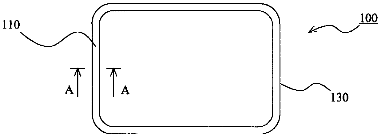
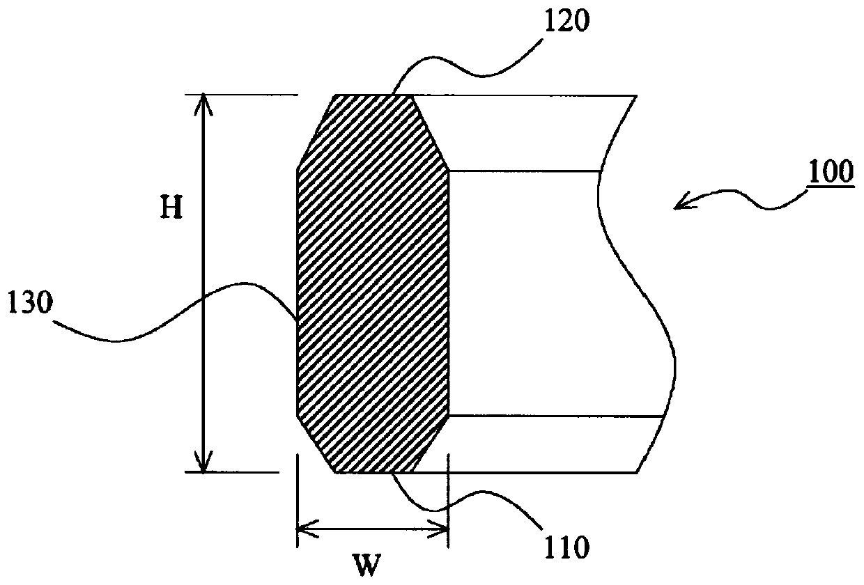
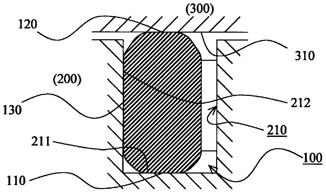
[0037] refer to Figure 1 to Figure 5 The sealing ring and the sealing structure of the embodiment of the present invention will be described. figure 1 It is a top view of the sealing ring according to the embodiment of the present invention. figure 2 It is a schematic cross-sectional view of the sealing ring of the embodiment of the present invention and is figure 1 Section A-A in . image 3 It is a schematic cross-sectional view for showing the state of the sealing ring of the embodiment of the present invention when it is in use. Figure 4 It is a figure for showing the state in the installation g...


PUM


Abstract

The present invention provides a sealing ring and a sealing structure that can stably exhibit sealing performance even under a high-temperature use environment. A sealing ring (100) is installed in an annular mounting groove (210) provided on the first component (200), and is in close contact with the bottom surface (211) and the second groove of the mounting groove (210) respectively. The end face (310) of the component (300) seals the gap between the first component (200) and the second component (300), and is characterized in that it is designed to seal the ring (100) under the highest temperature environment of the use environment. The circumference of the outer circumferential surface (130) is less than the circumference of the side wall surface (212) on the outer circumferential side of the mounting groove (210).

Description

technical field [0001] The present invention relates to a sealing ring and a sealing structure for sealing a gap between two components. Background technique [0002] In inverters or inverters mounted in hybrid electric vehicles (HV), electric vehicles (EV), fuel cell vehicles (FCV), etc., a sealing ring for waterproofing is provided between the case body and the cover body. That is, the case body and the cover are sealed by attaching the seal ring to the annular mounting groove provided in one of the case body and the cover body, and making the seal ring abut against the groove bottom surface of the mounting groove and the end surface of the other member. gap between the bodies. Furthermore, many of these case bodies or lids are made of aluminum die castings. Generally, the dimensional accuracy of aluminum die castings is not very high. In this case, by forming the cross-sectional shape of the seal ring to be longer in the vertical direction than in the horizontal direct...

Claims


Application Information

Patent Timeline
Patent Type & Authority Patents(China)
IPC IPC(8): F16J15/10
CPCF16J15/106F16J15/062F16J15/10F16J15/061F16J15/0887F16J15/3236
Inventor 古林润
Owner NOK CORP
Learn More