Fluked burying devices

A fluke and chain link technology, applied in the field of fluke embedding devices, can solve the problems of cost, handling and operation damage

Inactive Publication Date: 2017-02-22
BRUPAT
View PDF1 Cites 4 Cited by
  • Summary
  • Abstract
  • Description
  • Claims
  • Application Information

AI Technical Summary

Problems solved by technology

[0003] Disadvantages of the first fluke laying device include: slippage of the clamping components attaching the device to the wireline and handling and handling damage due to local bending of the wireline due to the lack of articulation at the front and rear ends of the device
[0004] Disadvantages of the second fluke laying device include: the requirement for structural accommodation of high transmitted loads in the mooring cable which greatly exceed the load contributed by the device; the need for expensive connecting shackles to provide a sufficient degree of protection when carrying high transmitted loads; Articulations; and classification societies' requirements to impose a high protective load on the device and shackle at the time of manufacture equal to that required for the associated chain cable

Method used


Image

  • Fluked burying devices
  • Fluked burying devices
  • Fluked burying devices

Examples


Embodiment Construction

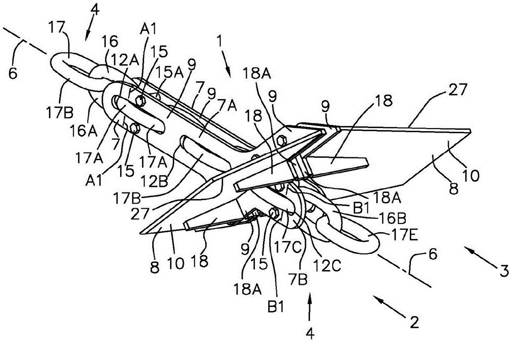
[0043] refer to Figure 1 to Figure 6 , the fluke embedding device 1 is formed by two parts 2, 3, that is, the fluke embedding device 1 comprises a port half 2 and a starboard half 3 arranged to surround the chain cable 4 and They are attached opposite each other in parallel with the chain cables 4 . The fluke embedding device 1 is about the symmetry plane 5 ( Figure 4 and Figure 5 ) symmetrical, the plane of symmetry 5 contains the axis 6 of the chain cable 4 which extends inwardly within its shank 7 . When the anchor fluke embedding device 1 is buried in the seabed 39 ( Figure 8 ) in the seabed soil 38, the plane of symmetry 5 is oriented vertically. The port half 2 and the starboard half 3 comprise a shank 7 and a fluke 8 . The handle 7 includes a front handle 7A extending to the front of the fluke 8 and a rear handle 7B extending to the rear of the fluke 8 . The shank 7 and the fluke 8 are respectively formed by a plate 9 and a plate 10 joined together at a joint ...


PUM


Abstract

A fluked burying device (1, 1A), for augmenting the burying and holding capability of a drag embedment marine anchor and chain cable system while being fixedly located thereon, comprises a fluke member (8) inclinedly attached to a body member (7) including pockets (12A, 12B, 12C) for accommodating links (16, 17) of a chain cable (4) passing there-through in a defined attitude such that axial and transverse loading is impressed in the chain cable (4) via separate links (17A, 17C) to maintain bending stresses therein similar to that occurring in a 5-pocket wildcat of a chain windlass and such that emergent links (16A, 16B) have sufficient articulation in service while embedded to permit the chain cable (4) to perform the function of and eliminate need for heavy expensive shackles. The fluked burying device (1, 1A) enables soil loading from a plurality thereof to be distributed along a length of chain cable (4) and is preferably provided with a body member (7) less wide than the effective footing width of a chain cable (4) and preferably split about a plane of symmetry (5) in two halves (2, 3) for ease of transport within container gauge.

Description

technical field [0001] The present invention relates to a cable mounted fluke embedding device for increasing both the penetration and retention capabilities of drag drop-in marine anchor and cable systems. Background technique [0002] Such a fluke embedding device is disclosed in U.S. Patent No. 3,685,479, which shows a first fluke embedding device for installation on a wire cable and for installation in a chain cable for embedding with the first fluke. The device forms a second fluke embedding device of an integral chain link. The fluke embedding device interacts with the seabed soil to exert an axial force in the cable, directly increasing the holding capacity. These devices also increase holding capacity indirectly by exerting a lateral force in the cable against its penetration resistance to facilitate deeper penetration of the anchor, thereby increasing in capacity. [0003] Disadvantages of the first fluke laying device include: slippage of the clamping components ...

Claims


Application Information

Patent Timeline
Patent Type & Authority Applications(China)
IPC IPC(8): B63B21/34B63B21/20
CPCB63B21/20B63B21/34B63B2021/262B63B21/26
Inventor 彼得·布鲁斯
Owner BRUPAT
Why Eureka
Try Eureka