Prosthetic foot

A prosthetic and forefoot technology, applied in the field of prosthetic feet, can solve the problem of inflexible heel spring response and achieve the effect of large deformability

Active Publication Date: 2017-02-22
OTTO BOCK HEALTHCARE IP GMBH & CO KG
View PDF24 Cites 7 Cited by
  • Summary
  • Abstract
  • Description
  • Claims
  • Application Information

AI Technical Summary

Problems solved by technology

A consequence of putting in the heel wedge is that the heel spring is less responsive

Method used


Image

  • Prosthetic foot
  • Prosthetic foot
  • Prosthetic foot

Examples


Embodiment Construction

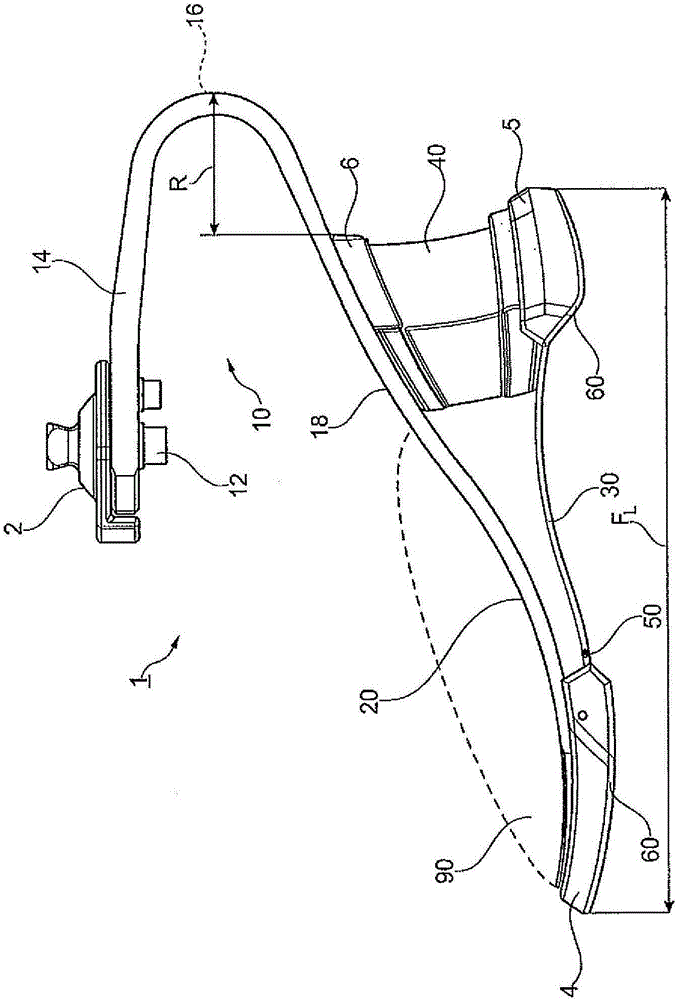
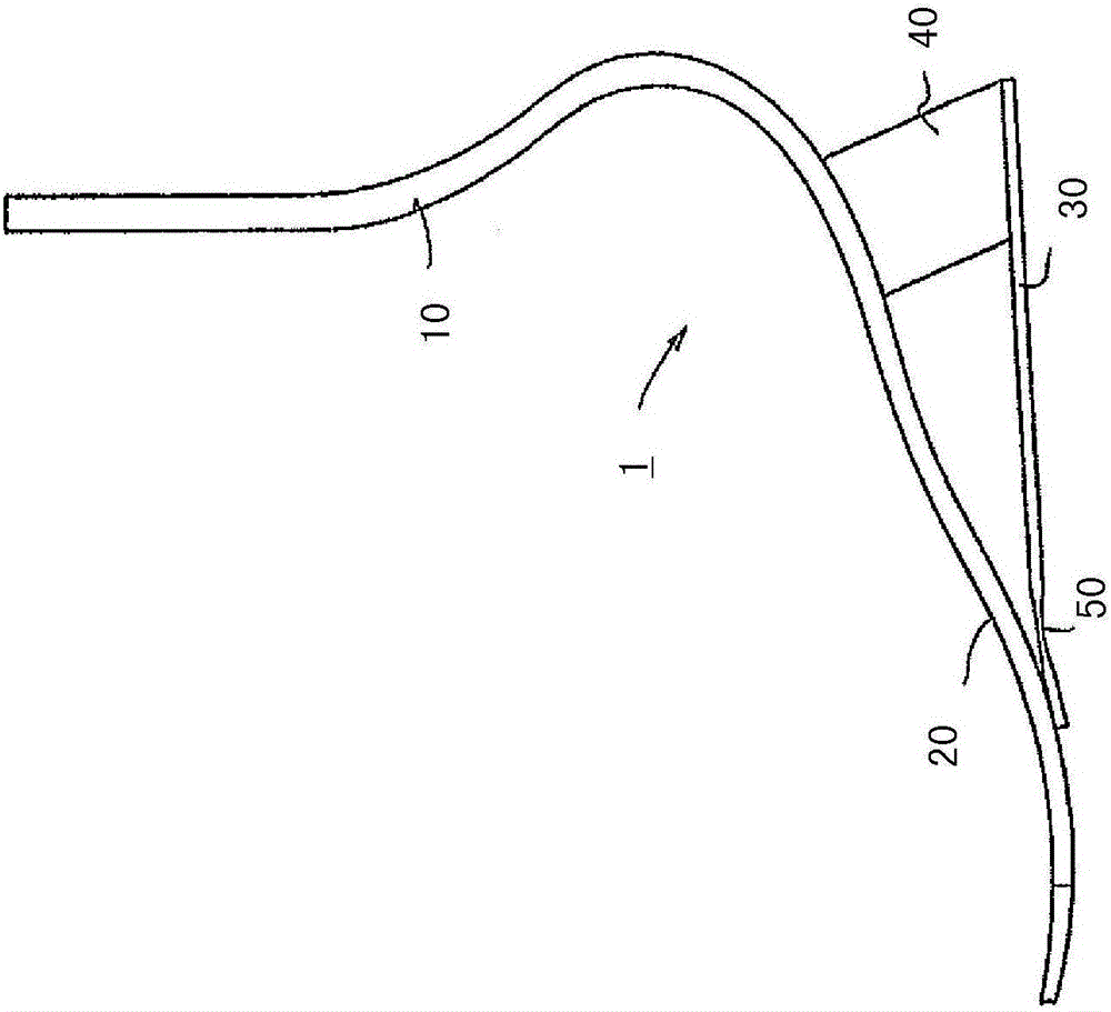
[0056] figure 1 In a perspective side view, a prosthetic foot 1 is shown with a structural component 10 in the form of a one-piece leaf spring, at the proximal end of which a connecting means 2 in the form of an adapter frame (Adapterpylon) is screwed fasten. This fastening takes place in the support section 14 , which is oriented substantially horizontally in the conventional arrangement of the prosthetic foot 1 . The structural component 10 extends rearwardly with a convex curvature in a bow 16 oriented in the rear direction from the connection means 2 to then extend in the front direction in a concavely configured connection section 18 . A convexly shaped forefoot section 20 , which protrudes into the area of ​​the toe of the prosthetic foot 1 , is again attached to the concave connecting section 18 . An orienting device 4 in the form of a cap is glued onto the toe region, said orienting device 4 having a sole element 60 on the underside or the sole element 60 being forme...


PUM


Abstract

The invention relates to a prosthetic foot with a structural component (10) having proximal attachment means (2) for fastening the prosthetic foot to a below-knee tube, a below-knee shaft or a prosthetic knee joint, with a forefoot portion (20) secured or formed on the structural component (10), and with a heel-side spring-damper system (40) which is assigned to the structural component (10) and which is compressed at a heel strike and bears on a sole-side guide element (30), wherein the structural component (10) is designed as a leaf spring which extends in a posterior direction from the proximal attachment means (2), forms an arch and is guided in an anterior and distal direction, wherein the arch protrudes posteriorly beyond the guide element (30).

Description

technical field [0001] The invention relates to a prosthetic foot comprising: a structural member having proximal connection means for fastening said prosthetic foot on a calf tube, a calf shaft or a prosthetic knee joint; a forefoot section; and a heel-side spring-damping system assigned to the structural component, which is compressed when the heel strikes and is supported on the sole-side guide element. The prosthetic foot is also suitable for being arranged in a shoe and is designed for this purpose. Background technique [0002] The prosthetic foot serves as the distal closure of the prosthetic device and can be fastened to a calf tube fastened to the prosthetic knee joint, directly to the prosthetic shaft or to the prosthetic knee joint. For this purpose, connecting means are usually provided on the proximal end of the prosthetic foot in order to produce a stable and continuous connection to the proximal prosthetic component. A prosthetic foot is usually provided wit...

Claims


Application Information

Patent Timeline
Patent Type & Authority Applications(China)
IPC IPC(8): A61F2/66
CPCA61F2/66A61F2002/5007A61F2002/5072A61F2002/665A61F2002/6657A61F2002/6671
Inventor M·普施J·诺尔特曼D·拉内C·默尼克N·A·威廉斯
Owner OTTO BOCK HEALTHCARE IP GMBH & CO KG
Why Eureka
Try Eureka