
Shock-absorption transformer

A technology for transformers and heat sinks, applied in the field of transformers, can solve the problems of transformers affecting work, difficult to restore deformation of heat sinks, and affecting service life.

Active Publication Date: 2017-02-22
吉林省至诚电气有限公司
View PDF5 Cites 11 Cited by
  • Summary
  • Abstract
  • Description
  • Claims
  • Application Information

AI Technical Summary

Problems solved by technology

The heat sink can dissipate the heat in the transformer, but if the temperature is too high, it will be difficult to restore the deformation of the heat sink, and even cracks will appear. The transformer is damaged and needs to be repaired, and the transformer will be affected by external vibration work, while affecting the service life, so it is necessary to improve

Method used


Image

  • Shock-absorption transformer

Examples


Embodiment Construction

[0018] The following are specific embodiments of the present invention and in conjunction with the accompanying drawings, the technical solutions of the present invention are further described, but the present invention is not limited to these embodiments.

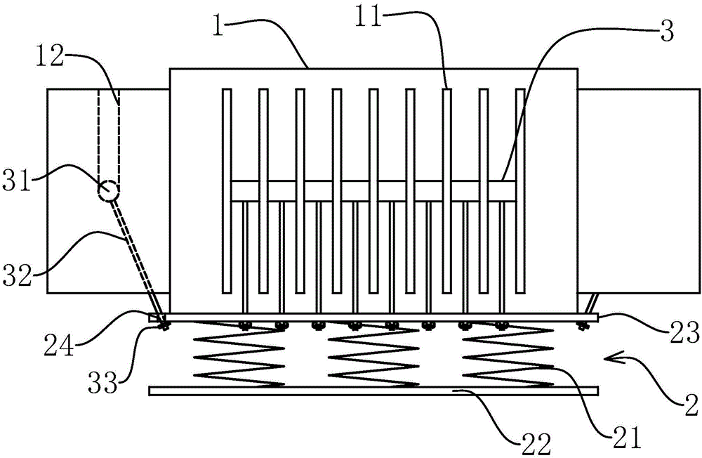
[0019] Such as figure 1 As shown, a shock-absorbing transformer of the present invention includes a transformer box body 1, a plurality of cooling fins 11 are fixed around the outside of the box body 1, and a plurality of cooling fins 11 corresponding to each side of the box body 1 are parallel to each other, and the two sides of the cooling fins 11 are parallel to each other. Strip slots 12 are respectively provided, and the slots 12 extend from the top of the heat sink 11 to the geometric center of the heat sink 11, and also include a shock absorber 2, the shock absorber 2 includes bottom plates that are parallel to each other and connected by shock absorbing springs 21 22 and a support plate 23, the bottom of the box bo...


PUM


Abstract

The invention provides a shock-absorption transformer and belongs to the field of transformers. The problems that cooling fins of an existing transformer are easy to deform, and overall strength is low are solved. The shock-absorption transformer comprises a box, multiple cooling fins are fixed around the outer side of the box, strip-shaped open grooves are formed in the two sides of each cooling fin respectively, the open grooves extend to the geometric centers of the cooling fins from the tops of the cooling fins, and the shock-absorption transformer further comprises a shock absorber; the shock absorber comprises a bottom plate and a supporting plate which are connected through shock-absorption springs, the bottom of the box is arranged on the supporting plate, multiple connecting holes are formed in the supporting plate, and the shock-absorption transformer further comprises multiple cushioning blocks with connecting rods; each cushioning block is provided with two supporting faces and arranged between the corresponding cooling fins, the two ends of each cushioning block slides to the bottom ends of the open grooves corresponding to geometric centers of the corresponding cooling fins from the top ends of the opposite open grooves of the corresponding adjacent cooling fins in a matched mode, the supporting faces abut against to the bottoms of the open grooves, and the ends, away from the cushioning blocks, of the connecting rods are fixed to the supporting plate through the connecting holes. The transformer is higher in strength and better in shock-absorption performance.

Description

technical field [0001] The invention belongs to the technical field of transformers and relates to a damping transformer. Background technique [0002] The transformer generally includes a box body, and the box body includes several box walls. Since the transformer will generate a lot of heat during operation, which will seriously affect the performance of the transformer, generally in order to reduce the heat inside the transformer, heat sinks are provided on the outside of the box wall. The heat sink can dissipate the heat in the transformer, but when the temperature is too high, it will be difficult to restore the deformation of the heat sink, and even cracks will appear. The transformer is damaged and needs to be repaired, and the transformer will affect the external vibration. Work, while affecting the service life, so it is necessary to improve. Contents of the invention [0003] The object of the present invention is to solve the above-mentioned problems in the pri...

Claims


Application Information

Patent Timeline
IPC IPC(8): H01F27/06H01F27/22
CPCH01F27/06H01F27/22
Inventor 乔兴友
Owner 吉林省至诚电气有限公司
Learn More