
Electrifying device for electricity control metering module

A metering module and electric device technology, applied in measuring devices, measuring electrical variables, measuring time integration, etc., can solve problems such as difficult adjustment, pressure application, poor contact, etc., achieve reasonable device design, improve work efficiency, and save time. Effect

Active Publication Date: 2017-02-22
ELECTRIC POWER RES INST OF STATE GRID ANHUI ELECTRIC POWER +2
View PDF5 Cites 1 Cited by
  • Summary
  • Abstract
  • Description
  • Claims
  • Application Information

AI Technical Summary

Problems solved by technology

[0003] Current power-on devices such as figure 1 As shown, when the power is turned on, the power control metering module a is pressed down, so that the power-on copper cylinder b is directly pressed on the power-on screw c to conduct electricity to realize power-on. This power-on method has the following disadvantages: (1) power-on The effect is not good, and the power-on copper cylinder b is in poor contact with the power-on screw c, resulting in poor power-on; (2) The distance between the power-on screw c and the bottom edge of the power control metering module a is too far, and it is not easy to adjust; (3) due to the electric energy The control metering module a is erected and compacted. Since the power control metering module a is relatively wide, it is difficult to position the power control metering module after it is erected, and it is also difficult to apply pressure to the center

Method used


Image

  • Electrifying device for electricity control metering module
  • Electrifying device for electricity control metering module
  • Electrifying device for electricity control metering module

Examples


Embodiment Construction

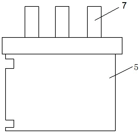
[0016] Such as figure 2 As shown, a power-on device for a power control metering module includes a power control metering module 1, at least one row of power-on screws 2 is installed on the bottom of the power control metering module 1, and a positioning device is installed on one side of the power control metering module 1 body. Locating pin 3; Also comprise base 4, first elastic support block 5 and second elastic support block 6 are fixedly set on base 4, first elastic support block 5 is provided with elastic support bar 7, and the upper end of elastic support bar 7 is connected with electric energy The bottom of the metering module 1 is controlled to be pressed tightly, and the second elastic support block 6 is provided with an electrification column 8 , and the upper end of the electrification column 8 is provided with an electrification tip 9 matched with the cross head of the electrification screw 2 . The positioning pin 3 makes the positioning of the electric energy co...


PUM


Abstract

The invention relates to an electrifying device for an electricity control metering module. The electrifying device for the electricity control metering module comprises the electricity control metering module, and further comprises a base, wherein at least one row of electrifying screws are mounted at the bottom of the electricity control metering module; a positioning pin for positioning the electricity control metering module is mounted on one side of the body of the electricity control metering module; a first elastic supporting block and a second elastic supporting block are fixedly arranged on the base; elastic supporting rods are arranged on the first elastic supporting block; the upper ends of the elastic supporting rods are tightly pressed against the bottom of the electricity control metering module; electrifying columns are arranged on the second elastic supporting block; electrifying tips matched with cross heads of the electrifying screws are arranged at the upper ends of the electrifying columns. The electrifying device for the electricity control metering module directly electrifies the electricity control metering module, so that the time for adjusting the electrifying device is saved; when the electrifying device electrifies the electricity control metering module, due to a reasonable design, the electrifying device is accurate in positioning, good in electrifying effect, fast and convenient and improves the working efficiency.

Description

technical field [0001] The invention relates to the technical field of electric energy metering, in particular to a power-on device for an electric energy control metering module. Background technique [0002] With the popularization and application of new energy sources in the automotive field, electric vehicles have sprung up like mushrooms after rain. Now, it has become a consensus that electric buses and electric cars replace traditional fuel vehicles. Therefore, electric vehicle charging piles have become a common demand in society. One of the main applications of electric energy control and metering modules is the application on electric vehicle charging piles. In addition, there are more colleges and universities, and there are more dormitory buildings in colleges and universities. In order to facilitate the management of electricity consumption in college dormitories, electric meter manufacturers have invented an electric energy control metering module, which can con...

Claims


Application Information

Patent Timeline
IPC IPC(8): G01R11/04
CPCG01R11/04
Inventor 张开明庄磊赵良德易鑫疏奇奇张宏生高寅梁晓伟黄丹丁建顺
Owner ELECTRIC POWER RES INST OF STATE GRID ANHUI ELECTRIC POWER
Learn More