
Accurately positioned and automatically packaged sample collector

A technology of precise positioning and sample collector, applied in the direction of sampling device, etc., can solve the problems of misalignment between the mouth of the sample barrel and the discharge flow pipe, inaccurate positioning of the sample barrel, difficulties in equipment manufacturing and installation, etc., and achieve the goal of eliminating human factors impact, simple and reliable workflow, and the effect of reducing water loss

Pending Publication Date: 2017-02-22
安阳新达高新技术开发有限公司
View PDF7 Cites 1 Cited by
  • Summary
  • Abstract
  • Description
  • Claims
  • Application Information

AI Technical Summary

Problems solved by technology

In the current sample collector, multiple sample barrels are set on the bottom plate, which is driven by the central shaft, and the central shaft is connected to the output of the reducer. Due to the gap during the transmission of the reducer, the drive bottom plate rotates There is often some error between the time and the set angle. Although the angle of this error is very small at the center of the bottom plate, the small error angle is V-shaped radially outward from the center, and the V-shaped mouth at the outer end is more Large, because the sample barrel is located at the radially outer end of the bottom plate, this small error angle will also cause a longer arc error length at the radially outer end, which often leads to inaccurate positioning of the sample barrel. At present In order to realize the informatization of the sampling system, IC cards are installed on the sample barrels of many sample collectors, and card readers are installed on the racks of the sample collectors. This error often causes the card readers to fail to find the IC cards and samples. Errors such as misalignment between the barrel mouth and the lower material flow pipe occur. To realize the packaging of the sample barrel mouth, accurate positioning during the rotation of the lower plate is the basic condition. At present, the central drive is used to realize the packaging of the sample barrel. Its packaging structure and driving structure are quite complicated. Due to the limited installation space on the upper part of the lower plate, this brings many difficulties to the manufacture and installation of the equipment. In addition, even after installation, the current packaging mechanism is often caused by inaccurate positioning of the lower plate. Work mistakes, and many packaging mechanisms currently designed are complex, immature, and have a high failure rate. At present, a better solution is needed in this regard

Method used


Image

  • Accurately positioned and automatically packaged sample collector
  • Accurately positioned and automatically packaged sample collector
  • Accurately positioned and automatically packaged sample collector

Examples


Embodiment Construction

[0009] In order to more fully explain the implementation of the present invention, implementation examples of the present invention are provided. These implementation examples are only illustrations of the present invention, and do not limit the scope of the present invention.

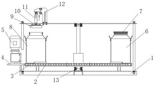
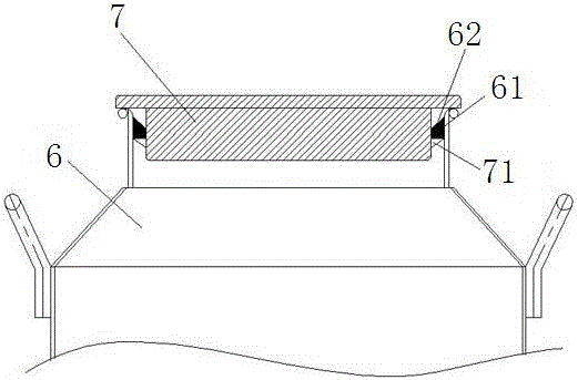
[0010] The present invention is further explained in detail in conjunction with the attached drawings. In the accompanying drawings, each mark is: 1: rack; 2: bottom plate; 3: chain; 4: sprocket; 5: motor; Limiting part; 62: Inclined surface; 7: Sample bucket one lid; 71: Lock bolt 8: Sample bucket two; 9: Sample bucket two lid; 10: Electromagnet; 11: Electric push rod; 12: Bracket; 13 : central rotation axis; 14: convex edge; as shown in the accompanying drawings, a precise positioning automatic packaging sample collector includes a sample collector frame 1 and a lower plate 2 for placing sample barrels, and the upper surface of the lower plate 2 is provided with Multiple sample barrel fixing positio...


PUM


Abstract

An accurately positioned and automatically packaged sample collector comprises a lower tray, wherein a circle of chain is fixedly arranged on the peripheral face of the lower tray, a rotary driving device is arranged on a rack beside the lower tray, a chain wheel is arranged on an output of the rotary driving device and is engaged with the chain, a bucket cover matched with a sample bucket is arranged and is provided with a lock, the lock is provided with an elastic lock tongue, a lock tongue limiting portion matched with the elastic lock tongue is arranged in a sample bucket opening, the bucket cover includes a metal irony layer, a linear driving device is arranged above a sample bucket stop position on the rack, the lower end of the linear driving device is connected with an electromagnet, the bucket cover can be sucked up after the electromagnet is electrified, and the electromagnet and the linear control device is connected to a control system. The accurately positioned and automatically packaged sample collector is accurate in positioning, stable in operation and reliable in performance.

Description

technical field [0001] The invention relates to a sample collector, in particular to a precise positioning automatic packaging sample collector, which belongs to the field of sampling mechanical equipment. Background technique [0002] The sample collector is used to put the effective material sample into the designated sample barrel. It is the last link in the bulk material sampling and quality inspection system before handing over the inspection. During the working process of the sample collector, not only must the positioning be accurate, Sampling is convenient. It is necessary to avoid the loss of moisture in the material sample, and to prevent the influence of human factors in the process of sample delivery, so as to prevent falsification. The sample collector has changed from the initial manual sample collector to the mechanical sample collector and then to the automatic collection The sampler has made considerable progress, but because the test results of the sample t...

Claims


Application Information

Patent Timeline
Patent Type & Authority Applications(China)
IPC IPC(8): G01N1/02
CPCG01N1/02
Inventor 赵焕普赵振峰
Owner 安阳新达高新技术开发有限公司
Learn More