
Automatic constant-temperature heating system and control method thereof

A technology of constant temperature heating and control method, applied in water heaters, fluid heaters, lighting and heating equipment, etc., can solve the problems of large volume, artificial irrigation, docking and sharing of purifying faucets, etc., to achieve a clean heating environment and reduce Bacteria growth and the effect of improving safety performance

Inactive Publication Date: 2017-02-22
陈非
View PDF10 Cites 9 Cited by
  • Summary
  • Abstract
  • Description
  • Claims
  • Application Information

AI Technical Summary

Problems solved by technology

However, the desktop temperature-controlled and adjustable boiling water machine not only occupies the desktop area, but also needs manual watering during use, and cannot be directly connected to the water purifier or direct water diversion. What is more serious is that the water in the water tank is prone to breed bacteria
The wall-mounted pipeline water boiler product is very large and cannot be shared with the clean water faucet.

Method used


Image

  • Automatic constant-temperature heating system and control method thereof
  • Automatic constant-temperature heating system and control method thereof
  • Automatic constant-temperature heating system and control method thereof

Examples


Embodiment 1

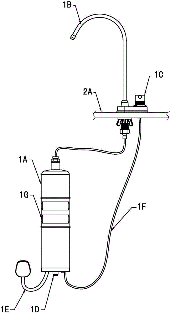
[0035] combine figure 1 and figure 2 As shown, an automatic constant temperature heating system includes a constant temperature heating unit 1A arranged under the table top 2A, an on-table control unit 1C and a water outlet unit 1B on the table top 2A, wherein the above-board control unit 1C is a knob switch 5, a water outlet The unit 1B is a faucet 4, and the rotary switch 5 is electrically connected to the constant temperature heating unit 1A through a signal line 1F. The water inlet 1D of the constant temperature heating unit 1A under the table is connected to pure water, and the constant temperature heating unit 1A is used for heating. The lower end of the constant temperature heating unit 1A is provided with a power cord 1E and a socket for connecting to a power supply. exist figure 1 Among them, the water inlet with external thread at the water outlet unit 1B on the stage is directly connected to the internal thread water outlet of the constant temperature heating uni...

Embodiment 2

[0061] According to the automatic constant temperature heating system proposed in the above embodiment, this embodiment proposes a control method for the automatic constant temperature heating system

[0062] Such as Figure 6 Shown, a kind of control method of automatic constant temperature heating system, comprises steps:

[0063] S1. When the user turns on the water flow through the knob switch 5 and sets the water temperature (that is, adjust the switch knob to the hot water level at this time, and adjust the temperature knob to the corresponding degree to set the corresponding water temperature), the knob switch 5. Transfer the water temperature setting value information to the controller 6;

[0064] S2. The controller 6 receives the water temperature setting value information, and obtains the outlet water temperature information sent by the temperature sensor 7, and the controller 6 judges the required water flow according to the water temperature setting value informat...


PUM


Abstract

The invention provides an automatic constant-temperature heating system and a control method thereof. The heating system comprises a current control device and a plurality of heating elements which communicate with each other through a pipeline, knob switches and a water faucet which is connected with water outlets of the heating elements, and further comprises a controller which is electrically connected with the knob switches, the current control device and the heating elements, wherein a temperature sensor which is electrically connected with the controller is arranged between the heating elements and the water faucet. Through the automatic constant-temperature heating system and the control method thereof, the effect of heating purified water in a water pipe at a constant temperature is achieved, and the water in the water pipe can be directly heated to a boiled water state without a water tank.

Description

technical field [0001] The invention relates to the field of water heaters, in particular to an automatic constant temperature heating system and a control method thereof. Background technique [0002] With the development of technology, automatic constant temperature heating is widely used in the field of water boilers, such as desktop temperature-controlled and adjustable water boilers and wall-mounted pipeline water boilers. However, the desktop temperature-controlled and adjustable boiling water machine not only occupies the desktop area, but also needs manual watering during use, and cannot be directly connected to the water purifier or direct water diversion. What is more serious is that the water in the water tank is prone to breed bacteria. However, the wall-mounted pipeline water boiler product is very large and cannot be connected and shared with the clean water faucet. Therefore develop a kind of heating system that can be directly connected with water purifier, ...

Claims


Application Information

Patent Timeline
IPC IPC(8): F24H1/10F24H9/20F24H9/18
CPCF24H1/101F24H9/1818F24H9/2028
Inventor 陈非朱科力林硕潘进军乔峰
Owner 陈非
Learn More