Constant-pressure valve capable of enabling partial pressure of water vapor to be constant

A water vapor partial pressure and constant pressure valve technology, applied in safety valve, balance valve, valve device and other directions, can solve the problems of inaccurate opening, large fluctuation of system humidity, fatigue damage of dehumidification unit, etc. The effect of slowing the penetration rate

Active Publication Date: 2017-02-22
WETKING CO LTD +1
View PDF12 Cites 1 Cited by
  • Summary
  • Abstract
  • Description
  • Claims
  • Application Information

AI Technical Summary

Problems solved by technology

Regardless of 0.05KPa or 0.2KPa, it is a very weak pressure value. In this micro-pressure range, most of the valve actions fail. They may be able to switch effectively in the laboratory environment or static environment, but in harsh environments Almost impossible to adapt, the valve will either fail quickly or cost a lot
In particular, the pressure difference of mechanical spring valves must be close to 1KPa to operate, and the error is huge. After a few movements, the spring may be deformed, and the elastic force may also change. The opening is not accurate. On the other hand, the spring valve with small elastic force cannot close properly Strict, for a system that may start and stop dozens or even more times a day, such valves have no use value; electronic valves are expensive, and their structures are complicated and cumbersome, including pressure sensor devices, control devices, The actuator, power supply, etc., and placed in the harsh external environment, if the protection measures are not in place, it is easy to be damaged
[0005] So far, no suitable products and good solutions have been found. Most of the main cable dehumidification systems have been running continuously since they were put into use. Increased power consumption and other issues have been plagued by bridge management departments

Method used


Image

  • Constant-pressure valve capable of enabling partial pressure of water vapor to be constant
  • Constant-pressure valve capable of enabling partial pressure of water vapor to be constant
  • Constant-pressure valve capable of enabling partial pressure of water vapor to be constant

Examples


Embodiment 1

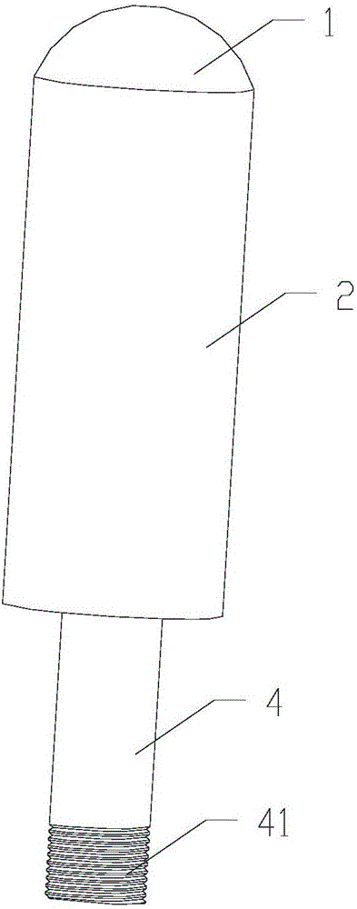
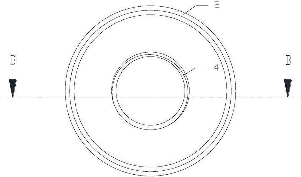
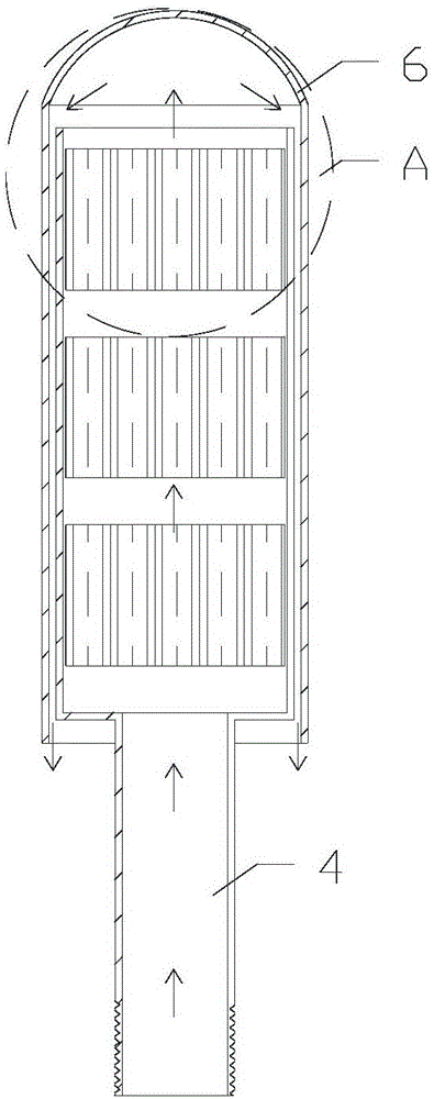
[0027] refer to Figure 1-2 , 4, a constant pressure valve with constant water vapor partial pressure, including a valve cover 1 and a valve body 2, the valve cover 1 is set on the valve body 2, and an exhaust passage 3 is left between the valve cover 1 and the valve body 2 . The shape of the silica gel inner core 5 is adapted to the shape of the inner wall of the valve body 2 , the valve body 2 is a cylinder, and the silica gel inner core 5 is a cylinder adapted to the shape of the inner wall of the valve body 2 . The length of the valve body 2 is 130-150 mm, and the width of the valve body 2 is 50-70 mm; the length of the valve body 2 in this embodiment is 135 mm, and the width is 57 mm.

[0028] One end of the valve cover 1 is a closed end, and the other end is an open end, and the valve body 2 extends into the valve cover 1 from the open end of the valve cover 1 . The open end of the valve cover discharges air along a 360° direction, which minimizes the exhaust being aff...

Embodiment 2

[0034] refer to image 3 , The closed end of the bonnet 1 is provided with an arc-shaped bonnet 6 for sheltering from wind and rain. The setting of the arc-shaped bonnet 6 can block the wind, rain and dust in all directions; when the wind blows, when the wind passes through the bonnet 1, the wind force is dispersed along the arc-shaped bonnet 6, which avoids the constant pressure valve being affected by the wind when it rains. Rainwater and dust fall on the arc-shaped bonnet 6 and slide down along the arc, preventing rainwater and dust from accumulating on the bonnet 1.

[0035] Other structures and connection methods are the same as in Embodiment 1.

experiment example

[0037] The present invention applies the constant pressure valve to Wuhan Gutian Bridge and Yingwuzhou Yangtze River Bridge. After more than one year of actual data monitoring, the following data are obtained:

[0038] Experiment 1

[0039] When the external water vapor partial pressure is 4KPa, the time for water vapor to penetrate into the main cable and cause the humidity to rise from 20%RH to 40%RH is shown in Table 1:

[0040] Table 1 Humidity schedule of water vapor penetration at 4KPa

[0041]

[0042] Experiment 2

[0043] When the external water vapor partial pressure is 2KPa, the time for water vapor to penetrate into the main cable and cause the humidity to rise from 20%RH to 40%RH is shown in Table 2:

[0044] Table 2 Humidity schedule of water vapor penetration at 2KPa

[0045]

[0046] It can be obtained from Table 1 and Table 2 that when the external water vapor partial pressure of the constant pressure valve of the present invention is 2KPa, water vapor ...


PUM


Abstract

The invention discloses a constant-pressure valve capable of enabling partial pressure of water vapor to be consistent. The constant-pressure valve comprises a bonnet and a valve body, wherein the bonnet sleeves the valve body; a ventilation channel is reserved between the bonnet and the valve body; one end of the bonnet is a closed end while the other end of the bonnet is an opening end; the valve body extends into the bonnet from the opening end of the bonnet; the inside of the valve body is hollow; an air inlet tube is arranged at one end of the valve body; the other end of the valve body is an open end; at least two silica gel inner cores are successively arranged in the valve body in the axial direction; and a gap is reserved between each two adjacent silica gel inner cores. The silica gel inner cores are arranged in the constant-pressure valve; when a system works, dry air under certain pressure enters from the air inlet tube, passes through the silica gel inner cores and takes away water in silica gel; and when the system does not work, water vapor of air of the outside enters from an air outlet, water of the water vapor is adsorbed by the multiple layers of silica gel inner cores, the water vapor is diffused among the multiple layers of silica gel inner cores in a Brownian movement mode, and therefore, the rate of permeation of the water vapor from outside to inside is greatly reduced.

Description

technical field [0001] The invention relates to the field of valves, in particular to a constant pressure valve with constant water vapor partial pressure. Background technique [0002] More and more new bridges are beginning to design the main cable dehumidification system. The old bridges that did not use the main cable dehumidification system have also raised the need to increase during the renovation. It has become a consensus to use the dehumidification system as the most effective anti-corrosion method for the main cable of the suspension bridge. The main cable Corrosion protection with dehumidification systems has become the standard practice. [0003] Whether it is the main cable dehumidification system from Europe or Japan, there is a problem that the dehumidification system cannot be shut down. The reason is that when the dehumidification system of the main cable is working, dry air with a certain pressure enters the main cable from the air intake clamp, and the d...

Claims


Application Information

Patent Timeline
Patent Type & Authority Applications(China)
IPC IPC(8): F16K17/20E01D19/16E01D22/00
CPCE01D19/16E01D22/00F16K17/20
Inventor 郭友谊姚超
Owner WETKING CO LTD
Why Eureka
Try Eureka