Eureka AIR delivers breakthrough ideas for toughest innovation challenges, trusted by R&D personnel around the world.

A Rotary Valve for Large Oxygen Concentrator

An oxygen generator and rotary valve technology, applied in the field of rotary valves, can solve the problems of inability to count the number of rotations of the rotary valve, inability to apply oxygen production equipment, inability to judge motor damage, etc., and to meet the requirements of gas circuit control, on-off precise effect

Active Publication Date: 2018-06-19
山东美迪宇能医疗科技有限公司
View PDF6 Cites 2 Cited by
  • Summary
  • Abstract
  • Description
  • Claims
  • Application Information

AI Technical Summary

Problems solved by technology

However, the coil of this kind of solenoid valve will make a sound when it is alternately switched on and off, and it will produce regular noise when it is applied to an oxygen generator; the rotary valve is generally composed of a stepping motor, a rotating disc and a stationary disc, and the rotary valve does not have The noise generated by the alternating energization of the electromagnetic coil can realize simultaneous control of multiple pipelines, but the existing rotary valve is only suitable for 1L household oxygen generators, and cannot be applied to large oxygen generators, and the existing rotary valves It is impossible to count the number of rotations of the rotary valve, and it is also impossible to judge whether the motor is damaged

Method used


Image

  • A Rotary Valve for Large Oxygen Concentrator
  • A Rotary Valve for Large Oxygen Concentrator
  • A Rotary Valve for Large Oxygen Concentrator

Examples


Embodiment Construction

[0019] The present invention will be further described below in conjunction with accompanying drawing by non-limiting embodiment:

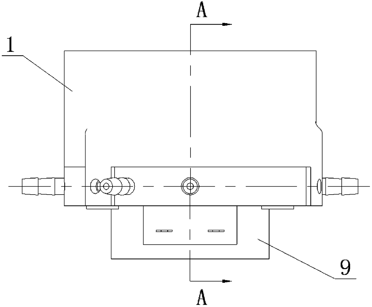
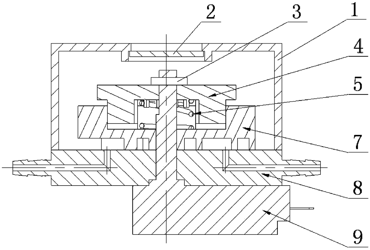
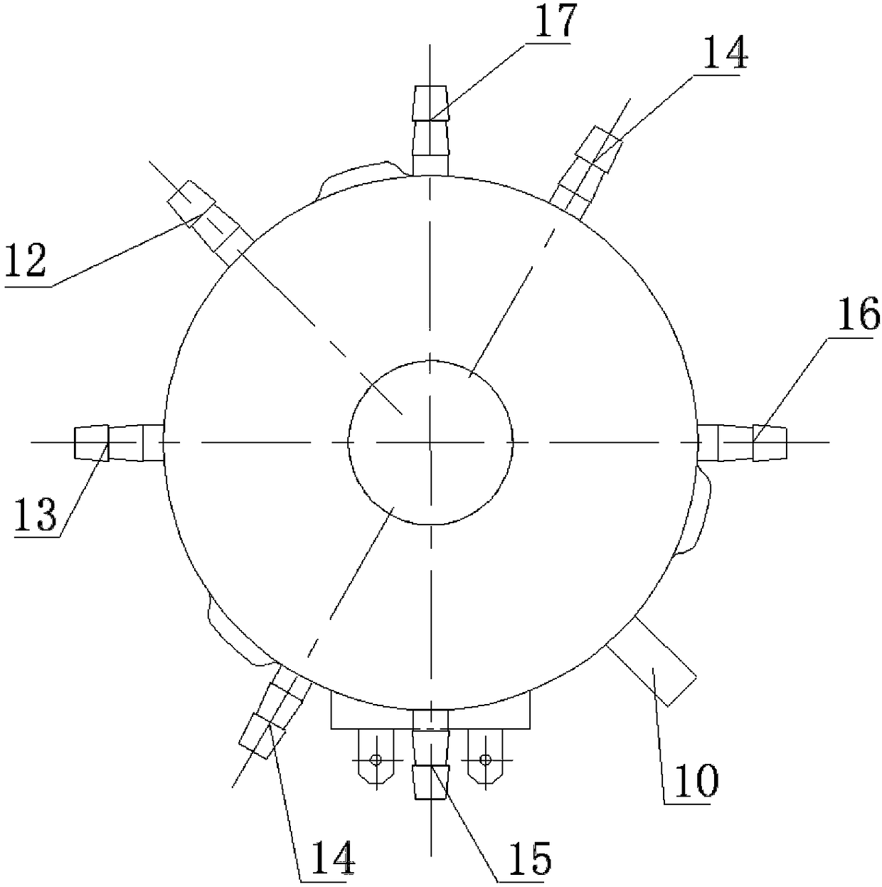
[0020] As shown in the attached figure, a rotary valve for a large oxygen generator includes a motor 9, a static piece 8, a moving piece 7, an outer spring 5, an inner spring 6, a transmission piece 4, a muffler cover 1, and a muffler piece 2 1. Proximity switch 10, the static plate 8, the moving plate 7, the outer spring 5, the inner spring 6, and the transmission plate 4 are successively set on the motor shaft of the motor 9 from bottom to top, and pass through the motor shaft through the pin shaft 3 , so that it is assembled as a whole, wherein, the inner spring 6 and the outer spring 5 make the moving piece 7 tightly pressed on the upper surface of the static piece 8 to form a seal, and the moving piece 7 is rotatably matched with the static piece 8, and the transmission The piece 4 cooperates with the moving piece 7 and can drive the moving p...


PUM


Abstract

The invention discloses a rotary valve for a large oxygenerator. The rotary valve comprises a stationary sheet, a movable sheet, springs and a transmission sheet which are assembled on a motor shaft. A silencing hood covers the outer side; a proximity switch is fixedly arranged on the side face of the silencing hood; an iron sheet is correspondingly arranged on the movable sheet; an air inlet hole, an air inlet control hole A, an air inlet control hole B, an exhaust control hole A, an exhaust control hole B and two balancing control holes are formed in the stationary sheet, wherein openings at one ends communicate with the upper surface of the stationary sheet; an air inlet channel, an exhaust channel and a balancing channel which are connected one another are arranged on the movable sheet; the balancing channel communicates with an air inlet groove; the air inlet hole communicates in the air inlet groove; the air inlet channel, the exhaust channel and the balancing channel are arranged when the movable sheet rotates to different positions, so that when the air inlet control hole A / the air inlet control hole B is connected to the air inlet channel, only the exhaust control hole B / the exhaust control hole A is connected to the exhaust channel, and when the air inlet control hole A and the air inlet control hole B are connected to the air inlet channel at the same time, only one of the balancing control holes is connected to the balancing channel.

Description

technical field [0001] The invention relates to a rotary valve for oxygen-generating equipment, which is mainly used for gas circuit control of the oxygen-generating equipment. Background technique [0002] The existing widely used PSA oxygen generator includes two adsorption towers A and B, and the two adsorption towers work alternately. In order for the oxygen generator to realize the alternate work of the adsorption tower, the control valve must be used to complete the commutation of compressed air and the desorption and discharge of nitrogen. At present, the commonly used control valves for oxygen generators mainly include solenoid valves and rotary valves. Among them, the solenoid valve adopts a diaphragm type solenoid valve. This type of solenoid valve adopts an upper and lower double diaphragm structure. The diaphragms are connected by a valve stem to form an interaction. The sealing between the valves and the switching of the main valve are realized by the upper an...

Claims


Application Information

Patent Timeline
Patent Type & Authority Patents(China)
IPC IPC(8): F16K11/074F16K31/04F16K37/00
CPCF16K11/0743F16K31/042F16K37/0083
Inventor 冯凯原铮吴洪刚刘正强
Owner 山东美迪宇能医疗科技有限公司
Why Eureka
Eureka Blog
Learn More