Eureka AIR delivers breakthrough ideas for toughest innovation challenges, trusted by R&D personnel around the world.

Novel door and window damping limiting wind brace

A wind bracing and damping technology, applied in the direction of building fasteners, wing fan fasteners, buildings, etc., can solve the problems of easy wear and tear of the damping structure, unsatisfactory effect, easy to make loud noises, etc., and achieve firm installation. , convenient production process, easy to use effect

Inactive Publication Date: 2017-02-22
SHANDONG JUNQIANGBONA HARDWARE TECH CO LTD
View PDF6 Cites 1 Cited by
  • Summary
  • Abstract
  • Description
  • Claims
  • Application Information

AI Technical Summary

Problems solved by technology

[0002] Doors, windows and other devices that are easily blown by the wind often produce excessive switching action due to excessive wind force or artificial switching force, which is prone to loud noises, violent collisions, and even damage to doors and windows or damaged
Existing doors and windows are equipped with connection structures that connect the door and window sash and the door and window frame, but few doors and windows are connected by damping structures, and most of the existing damping structures are more complicated, larger in size, and the effect is often not ideal
In particular, the existing common damping structure generates damping force through slide rails and sliders, and the doors and windows are fixed by hand-tightened screws. The damping structure is very easy to wear and needs to be replaced frequently, resulting in high cost of use.

Method used


Image

  • Novel door and window damping limiting wind brace
  • Novel door and window damping limiting wind brace

Examples


Embodiment Construction

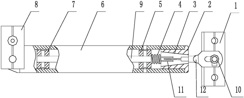
[0019] The following describes the present invention in detail in conjunction with the accompanying drawings and examples: Embodiment: Referring to the accompanying drawings, a novel door and window damping limit wind brace is provided with a fan fixing part 8, a frame fixing part 1 and a wind brace main body, and the wind brace main body is provided with There is a wind brace outer tube 6, and one end of the wind brace outer tube is provided with a damping fixing part 2, and the middle of the damping fixing part is provided with a trumpet-shaped inner cavity with a thickness inside and a thinner outside, and a conical cone matching the inner cavity is arranged in the inner cavity The body-shaped damper 3 is provided with an expansion-contraction cavity 11 in the body of the damper. The structure of the expansion-contraction cavity is: expansion and contraction with the pressure of the damper; Pull rod 9, a damping block 7 is arranged between the pull bar and the outer tube of ...


PUM


Abstract

The invention relates to a novel door and window damping limiting wind brace which is equipped with a fan fixing part, a frame fixing part and a wind brace main body, wherein the wind brace main body is equipped with a wind brace outer pipe; one end in the wind brace outer pipe is equipped with a damping fixing part; an inner cavity is arranged in the middle of the damping fixing part; a cone-shaped damper is arranged in the inner cavity; an expanding-shrinking cavity is arranged in the damper body; a drawbar is arranged at the inner end of the damper; a damping gear block is arranged between the drawbar and the wind brace outer pipe; one end, connected with the damper, of the drawbar is equipped with a damping pressure spring which is tightened between the damping gear block and the damper; the other end of the drawbar is connected with the fan fixing part; and the outer end of the damping fixing part is connected with the frame fixing part. The novel door and window damping limiting wind brace is suitable for being used as the damping limiting wind brace of doors and windows as well as other wind-driving opening-closing equipment, can generate very gentle buffer effect to prevent doors and windows from being fiercely opened, closed and collided; doors and windows can be stabilized on each position, so that the doors and windows are protected very well; and the novel door and window damping limiting wind brace is convenient to use, is convenient and flexible to mount, and can greatly prolong the service lives of the doors and windows.

Description

technical field [0001] The invention relates to the technical field of construction equipment, in particular to a damping limit wind brace used on doors, windows or other equipment. Safety features of other devices. The invention is suitable for doors, windows or other switchgears that may be blown by wind, and has novel structure, firm installation, good performance and wide application range. Background technique [0002] Doors, windows and other devices that are easily blown by the wind often produce excessive switching action due to excessive wind force or artificial switching force, which is prone to loud noises, violent collisions, and even damage to doors and windows or damaged. Existing doors and windows are all provided with a connection structure that connects the door and window sash and the door and window frame, but few doors and windows are connected by a damping structure, and most of the existing damping structures are more complicated, larger in size, and ...

Claims


Application Information

Patent Timeline
IPC IPC(8): E05C17/30
CPCE05C17/30
Inventor 化明杰李俊英李洪斌郭淑静化风强
Owner SHANDONG JUNQIANGBONA HARDWARE TECH CO LTD
Why Eureka
Eureka Blog
Learn More