Pull-rod spiral spring damper with presettable early-stage rigidity

A technology of coil springs and dampers, applied in protective buildings/shelters, building components, building structures, etc., can solve the problems of resource waste, reduce shock absorption costs, and inappropriateness, and achieve shortened length and reduced insulation shock cost effect

Pending Publication Date: 2017-02-22
ANHUI XINZE TECH CO LTD
View PDF8 Cites 4 Cited by
  • Summary
  • Abstract
  • Description
  • Claims
  • Application Information

AI Technical Summary

Problems solved by technology

However, this utility model patent obviously has the following disadvantages: 1. Two coil springs are required, and the length of the entire damper is relatively long, which is not suitable for installation in a space with a small distance; 2. It is difficult or even impossible to ensure the two springs in the process Only the stiffness of the spring (including tensile stiffness and compression stiffness) is equal, so the shock absorption effect is different in different wind directions; 3. The early stiffness of the damper cannot be changed to achieve the preset wind resistance level and reduce the cost of shock absorption; 4. A helical spring works in two states of tension and compression at the same time. The metal material and production process of the existing spring are difficult to meet the requirements. The two working states of tension and compression can only be realized by reducing the elastic deformation range of the helical spring. , which obviously wastes resources
It can be seen that although the stiffness of the spring in the patent application scheme can be changed, the effective working length of the spring is not only significantly shortened, but also can only be compressed for energy consumption and vibration reduction, and cannot be stretched for energy consumption and vibration reduction.
In addition, the stiffness of the spring is changed by changing the effective working length of the spring. The adjustment range is limited by the material and shape of the spring itself.

Method used


Image

  • Pull-rod spiral spring damper with presettable early-stage rigidity
  • Pull-rod spiral spring damper with presettable early-stage rigidity
  • Pull-rod spiral spring damper with presettable early-stage rigidity

Examples


example 1

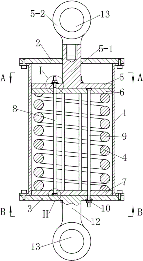
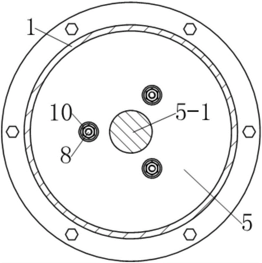
[0025] see figure 1 , the tie-rod coil spring damper with preset early rigidity in this example is an energy-dissipating device that can be used for aseismic reinforcement of building structures. 2 and the second end cover 3, wherein, the first end cover 2 and the second end cover 3 are respectively fixedly connected to the two ends of the guide sleeve by screws. A cylindrical helical compression spring 4 is arranged in the axial direction in the guide sleeve 1, and a drive member extends into the guide sleeve 1 from the center of the first end cover 2; wherein, the drive member is located on a cylindrical The upper end of the helical compression spring 4 is composed of a dynamic pressure plate 5 that is in motion with the guide sleeve 1 and a drive rod 5-1 that extends upward from the upper surface of the dynamic pressure plate 5 to extend out of the guide sleeve 1. The drive rod 5-1 is located outside the guide sleeve 1. The end is provided with a connecting ring 5-2 with ...

example 2

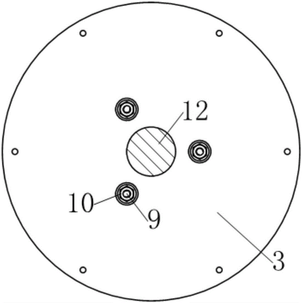
[0034] see Figure 6-8 , the tie-rod coil spring damper with preset early stiffness in this example is a kind of vibration isolation device (also called seismic isolation support) that can be used for vertical vibration isolation of buildings. Compared with Example 1, this example mainly has The difference is as follows:

[0035] 1. As a vibration isolation support, in order to facilitate installation, the connecting rod provided on the second end cover 3 in Example 1 is omitted in this example, and the second end cover 3 is extended axially downward from the edge and then outward It extends radially, and is evenly provided with connecting bolt holes 15 at the edge. The second end cover 3 is used as the base of the shock-isolation support, and the length of the downward axial extension needs to be greater than that of the second group of polished rod bolts 9. The length of the outer portion of the second end cap 3 . The driving rod 5-1 of the driving member is a metal tube e...


PUM


Abstract

The invention discloses a pull-rod spiral spring damper with the presettable early-stage rigidity. The pull-rod spiral spring damper is characterized in that an adverse pressing device is further arranged in a guide sleeve and comprises two sets of prepressing pull rods and two floating pressing plates; one of the two floating pressing plates is arranged between a movable pressing plate and a cylindrical spiral compression spring, and the other one of the two floating pressing plates is arranged between a second end cover and the cylindrical spiral compression spring; the two sets of prepressing pull rods are respectively distributed in a center hole of the cylindrical spiral compression spring, one ends of one set of prepressing pull rods are respectively fixed onto the floating pressing plate adjacent to the movable pressing plate, and the other ends of the set of prepressing pull rods penetrate through the floating pressing plate adjacent to the second end cover and the second end cover and are fixed onto a limiting element; one ends of the other set of prepressing pull rods are respectively fixed onto the floating pressing plate adjacent to the second end cover, and the other ends of the set of prepressing pull rods respectively penetrate through the floating pressing plate adjacent to the movable pressing plate and the movable pressing plate and are fixed onto a limiting element.

Description

technical field [0001] The present invention relates to shock absorbing devices, and more particularly to dampers employing helical compression springs. Background technique [0002] A damper is a shock-absorbing device that consumes motion energy by providing motion resistance. The use of dampers for energy dissipation and shock absorption is a traditional technology widely used in industries such as aerospace, aviation, military industry, guns, and automobiles. Since the 1970s, people have gradually applied the technology of using dampers to consume energy and reduce shocks to structural engineering such as buildings, bridges, and railways. The coil spring damper is widely used in the anti-seismic structures of various buildings because of its high impact resistance, low cost and good shock absorption effect. [0003] People pursue a comprehensive anti-seismic performance combining "resistance" and "loss" for the design of buildings, especially the anti-seismic structure...

Claims


Application Information

Patent Timeline
Patent Type & Authority Applications(China)
IPC IPC(8): E04B1/98E04H9/02
CPCE04H9/021E04H9/0215
Inventor 沈珊胡济福胡济全
Owner ANHUI XINZE TECH CO LTD
Why Eureka
Try Eureka