
3D printing head with pressure sensing high-temperature-resisting pulp

A technology with high temperature resistance and printing head, applied in the field of 3D printing head, it can solve the problems of narrow application range, equipment damage, and difficulty in maintenance and cleaning of 3D printing head, so as to achieve the effect of solving the difficulty of maintenance and cleaning.

Inactive Publication Date: 2017-02-22
CHINA UNIV OF GEOSCIENCES (WUHAN)
View PDF3 Cites 8 Cited by
  • Summary
  • Abstract
  • Description
  • Claims
  • Application Information

AI Technical Summary

Problems solved by technology

First: Monitor the extrusion pressure value of the 3D printing head when extruding the slurry through the extrusion force value of the push rod on the pressure sensor, which can effectively solve the problem of equipment damage caused by continuous extrusion in the plugged state, and also timely Understand the pressure value and its change law required for 3D printing slurry extrusion under different formulations, so as to provide important research data in the development of 3D printing slurry consumables and 3D printing scientific experiment research; second: extrusion push rod module, The insulation bin module, material storage module and discharge module are made of metal materials, high temperature resistant heat insulation materials and high temperature resistant sealing materials, so that the 3D printer can be filled with high temperature molten slurry up to about 400 degrees, which effectively solves the problem of 3D printing. The problem of narrow application range of materials; third: the structure of the discharge module is simple and easy to disassemble, which effectively solves the problem of difficult maintenance and cleaning of the 3D printing head

Method used


Image

  • 3D printing head with pressure sensing high-temperature-resisting pulp
  • 3D printing head with pressure sensing high-temperature-resisting pulp
  • 3D printing head with pressure sensing high-temperature-resisting pulp

Examples


Embodiment Construction

[0029] The present invention will be further described below in conjunction with drawings and embodiments.

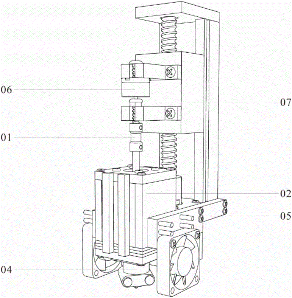
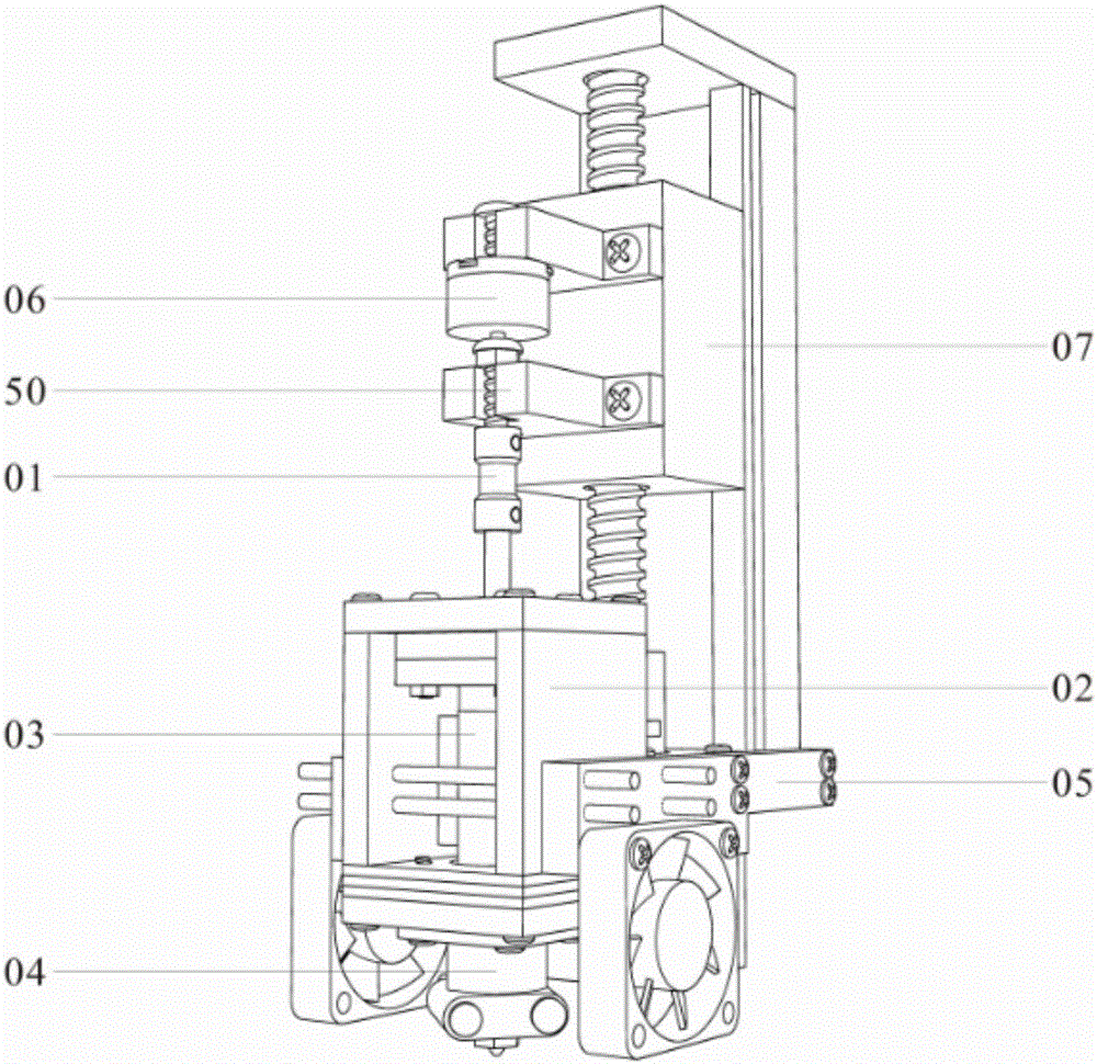
[0030] The invention provides a 3D printing head with pressure-sensitive and high-temperature-resistant slurry, which is installed on a three-axis linkage platform. Figure 1 to Figure 4 , including a linear displacement mechanism module 07, a connection module 05, a thermal insulation bin module 02, a discharge module 04, a material storage module 03, a pressure sensor module 06, and an extrusion push rod module 01. The transmission module 07 is installed on the ready-made three-axis linkage platform (not shown), one end of the connection module 05 is set on the transmission module 07, the other end is set on the heat insulation bin module 02, and the discharge module 04 is placed in the heat insulation bin On module 02, the ejection direction of the discharge module 04 points to the printing plane of the three-axis linkage platform (not shown), and the storage module ...


PUM


Abstract

The invention provides a 3D printing head with pressure sensing high-temperature-resisting pulp. The 3D printing head is arranged on a three-shaft linkage platform and comprises a storage module and a discharging module. The storage module is located in a heat isolation bin module. The heat isolation bin module is a cuboid bin, and each of an upper bin plate and a lower bin plate of the heat isolation bin module is provided with a through hole. The lower end of the storage module is connected with the discharging module through the through hole of the lower bin plate, wherein the discharging module is located below the heat isolation bin module. The spraying direction of the storage module points at the printing plane of the three-shaft linkage platform. The upper end of the storage module is connected with the lower end of an extrusion push rod module through the through hole of the upper bin plate. The upper end of the extrusion push rod module is connected with a linear displacement mechanism module doing the vertical movement through a pressure sensing module. According to the 3D printing head, the pressure is detected according to the extrusion force of the push rod on a pressure sensor, and the problem of damage on equipment due to continuous extrusion in a plugging state is effectively solved; and meanwhile, the discharging module and the storage module are simple in structure and easy to detach, and the problem that the 3D printing head is difficult to maintain and clean is effectively solved.

Description

technical field [0001] The invention relates to a 3D printing head with pressure-sensitive and high-temperature-resistant slurry, which belongs to the technical field of printing. Background technique [0002] 3D printing technology is a new type of layer-by-layer superposition technology, which is now mainly used in industrial-grade metals, ceramics, polymers, etc., and is still small-batch and personalized production and processing. Printing 3D models by injection extrusion is one of the current methods of 3D printing models. However, at present, this printing method cannot detect the clogging problem in the printing process in time, resulting in damage to the equipment caused by continuous extrusion in the clogging state. At the same time, there are also the problems of narrow application range of printing materials and difficulty in cleaning and maintaining equipment. Contents of the invention [0003] In order to solve the deficiencies of the prior art, the present ...

Claims


Application Information

Patent Timeline
Patent Type & Authority Applications(China)
IPC IPC(8): B29C64/20B29C64/30B33Y30/00B33Y50/02
CPCB33Y30/00B33Y50/02
Inventor 郝亮熊玮
Owner CHINA UNIV OF GEOSCIENCES (WUHAN)
Learn More