Variable gap-adjusting device

A gap adjustment device and variable technology, applied in the direction of mechanically driven excavators/dredgers, etc., can solve the problems of excavator durability decline, time waste, shaking, etc., and achieve improved convenience, stability and strong support Effect

Inactive Publication Date: 2017-02-15
林士铉
View PDF3 Cites 0 Cited by
  • Summary
  • Abstract
  • Description
  • Claims
  • Application Information

AI Technical Summary

Problems solved by technology

However, in order to effectively support the gap between the arm 8 and the bucket 9, it is very cumbersome to replace or correct the above-mentioned support device according to the gap width, and the frequent above-mentioned replacement operations will also cause a lot of waste of time.
[0014] In addition, even if the gap caused by the continuous wear is dealt with through the replacement or correction of the above-mentioned support device, it can only be a temporary solution, because the continuous wear and tear during the operation process, the above-mentioned arm 8 and There will always be a gap between the buckets 9
In particular, the above-mentioned clearance will cause the sway of the bucket 9 for carrying heavy loads, causing a continuous burden on the above-mentioned bucket 9 or the structure such as the arm 8 or the hydraulic mechanism 6, which will lead to the durability of the excavator. Serious problems with sexual decline
[0015] In addition, when attaching a working tool such as a crusher or a cutting machine to the end of the arm 8 instead of the bucket 9, since the gap between each working tool and the arm is different, it is necessary to combine it according to the gap each time. The corresponding support plate, which causes a lot of inconvenience

Method used


Image

  • Variable gap-adjusting device
  • Variable gap-adjusting device
  • Variable gap-adjusting device

Examples


Embodiment Construction

[0026] The best implementation form of the present invention will be described in detail in the following content with reference to the accompanying drawings.

[0027] In the following, the variable gap adjusting device applicable to the preferred embodiment of the present invention will be described in detail with reference to the accompanying drawings.

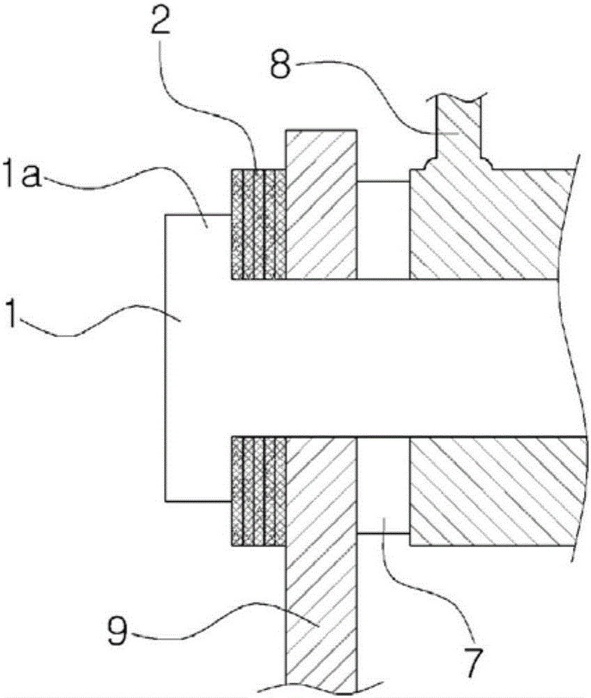
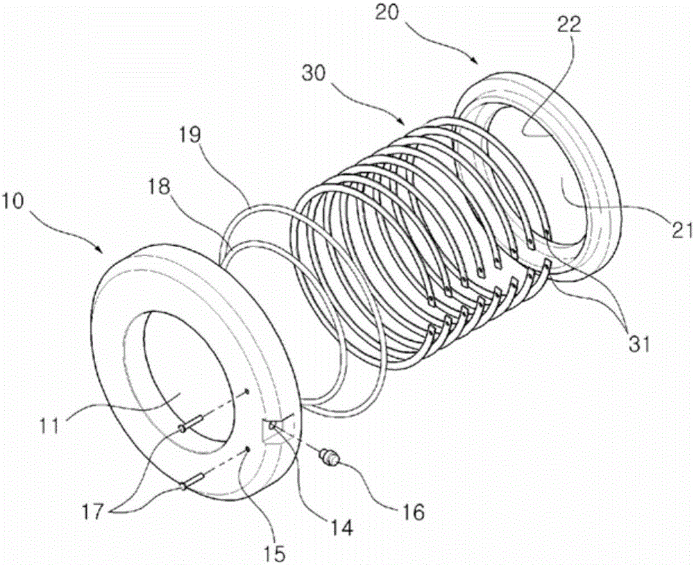
[0028] image 3 It is an exploded oblique view of a variable clearance adjusting device applicable to one embodiment of the present invention, Figure 4 and Figure 5 It is a schematic diagram of the connecting parts of the various structures of the variable gap adjusting device applicable to one embodiment of the present invention, Figure 6 It is a schematic diagram of the combined state of the guide plate and the gap supporting snap ring to which one embodiment of the present invention is applied.

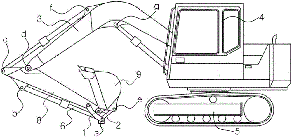
[0029] Such as Figure 3 to Figure 6 As shown, the variable gap adjustment device 100 applicable to the present inventio...


PUM


Abstract

In order to improve durability and stability while supporting a gap between both side structures connected by a rotary shaft and moving relative to each other, the present invention provides a variable gap-adjusting device inserted between a first structure and a second structure, rotatably connected by the rotary shaft and moving relative to each other, so as to support a gap between facing surfaces of the first structure and the second structure, the device comprising: a base disc having a first hole, which is formed in the center part thereof and through which the rotary shaft passes, and a guide groove part formed along a circumferential direction of a first surface corresponding to one of the facing surfaces; a guide disc having a second hole, which is formed in the center part thereof and through which the rotary shaft passes, and a guide protrusion part inserted into the guide groove part, protruding from the surface facing the first surface of the base disc, and having a mounting surface formed at the end portion thereof to correspond to a bottom surface of the guide groove part; a valve provided in an injection hole, which is formed at the lateral side of the base disc, in order to inject working fluid into the guide groove part such that the base disc and the guide disc are spaced apart from each other; and a plurality of gap-supporting snap rings arranged by being stacked along the lateral side of the guide protrusion part, such that the snap rings are arranged between the mounting surface and the bottom surface of the guide groove part by means of elastic restoring force when a space is formed between the base disc and the guide disc according to the injection of the working fluid.

Description

technical field [0001] The present invention relates to a variable gap adjustment device, in particular to a variable gap adjustment device that supports the gap between two structures on both sides that are connected by a rotating shaft and that move relative to each other while improving its durability and stability. device. Background technique [0002] Generally, when two different structures are connected by rotating shafts in construction equipment and industrial equipment, joints ( Seam) or bushing (bush) and other supporting devices. [0003] At this time, the above-mentioned support devices such as joints or bushes can prevent direct contact between the above-mentioned structures and prevent damage due to wear, and can be embedded in the above-mentioned rotating shaft in the form of being arranged between the above-mentioned structures. , preventing the occurrence of gaps between the above-mentioned respective structures. [0004] For example, an excavator used f...

Claims


Application Information

Patent Timeline
Patent Type & Authority Applications(China)
IPC IPC(8): E02F3/36
CPCE02F3/36
Inventor 林永宰
Owner 林士铉
Why Eureka
Try Eureka