
Gripping jaw safety device with tongue and groove for HRC

A workpiece and robot arm technology, applied in the field of grasping devices, can solve problems such as gripper damage

Inactive Publication Date: 2017-02-15
KUKA SYSTEMS
View PDF10 Cites 2 Cited by
  • Summary
  • Abstract
  • Description
  • Claims
  • Application Information

AI Technical Summary

Problems solved by technology

If the actuator is operated at this time, the jaws may cause serious injury during their movement

Method used


Image

  • Gripping jaw safety device with tongue and groove for HRC
  • Gripping jaw safety device with tongue and groove for HRC
  • Gripping jaw safety device with tongue and groove for HRC

Examples


Embodiment Construction

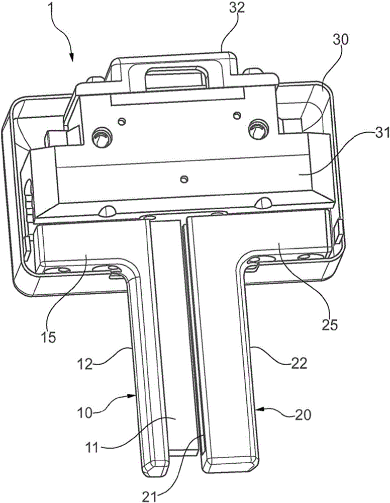
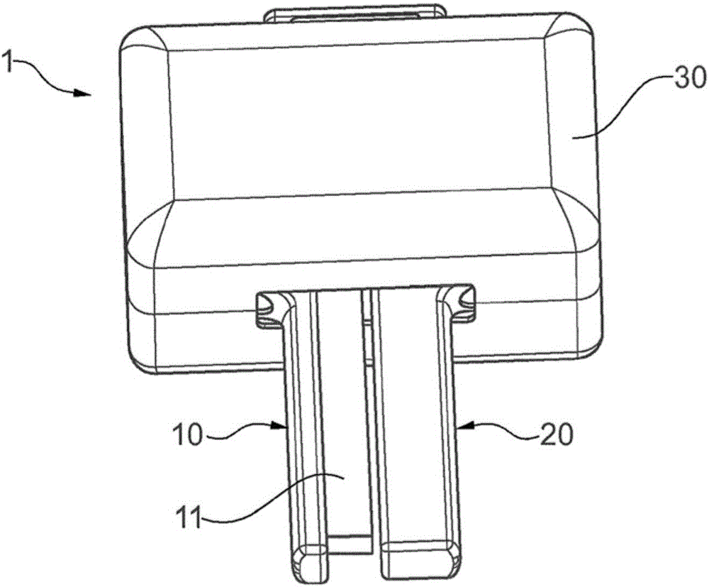
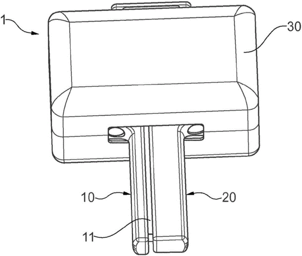
[0019] figure 1 A three-dimensional view of the gripping device 1 according to the invention is schematically shown with the housing 30 partially opened. The gripping device 1 has two jaws 10 and 20 which are arranged to be movable relative to each other. As can be seen by a person skilled in the art, the gripping device 1 shown in the figure is a bifurcated gripping device, which is designed to be introduced into the inner space or hollow space of the workpiece and pass through The movement of the two gripper jaws 10 and 20 away from each other, or divergence, grips the workpiece. The two jaws are rod-shaped and run parallel. The first jaw 10 has a tenon projection 11 on the side facing the second jaw 20 . The tenon projection 11 is formed integrally with the clamping jaw 10 , but can also be a separate part which is arranged or fixed on the first clamping jaw 10 . The second clamping jaw 20 has a groove on the side facing the first clamping jaw, which groove is designed ...


PUM


Abstract

The present invention relates to a gripping device (1), in particular as effector for an industrial robot, comprising first (10) and second (20) clamping jaws which are movable relative to each other to engage a workpiece. The first clamping jaw (10) has a tongue projection (11) and the second clamping jaw (20) has a corresponding groove (21) which at least partly accommodates the tongue projection (11) when the clamping jaws (10, 20) are moved towards each other in order to prevent objects or body parts from being accidentally inserted in the space between the clamping jaws.

Description

technical field [0001] The invention relates to a gripping device, which is designed in particular as an actuator for an industrial robot and which is equipped with mechanical protection; the invention also relates to a robotic system comprising such a gripping device, And a method for gripping a workpiece provided with a hollow space. Background technique [0002] Industrial robots are programmable machines which are designed to automatically manipulate or process objects or workpieces. A typical example is a so-called articulated robot, which has several articulated limbs which are connected to one another via joints. In its simplest form, such a robot has a frame on which a so-called turntable is rotatably arranged. On the turntable, the first arm of the robot, which is also referred to as the rocker arm, is connected via a further swivel joint. A further arm is provided on the rocker arm via a further swivel joint, which is provided at its free end with a receptacle f...

Claims


Application Information

Patent Timeline
Patent Type & Authority Applications(China)
IPC IPC(8): B25J15/00B25J15/02B25J19/06
CPCB25J15/0047B25J15/02B25J15/0253B25J19/06
Inventor 朱利安·斯德克斯切兰德Z·伯扎达T·马里斯
Owner KUKA SYSTEMS
Learn More