Microcircuit module back side pre-soldering and pre-soldering heating device

A microcircuit and backside technology, which is applied in printed circuit, printed circuit manufacturing, printed circuit assembly of electrical components, etc., can solve the problems that affect the welding reliability of components, reduce the service life, and the solder is easy to oxidize, so as to ensure reliability and stability, save the amount of solder, reduce the effect of solder oxidation

Inactive Publication Date: 2017-02-15
ZHUZHOU TIANWEI TECH CO LTD
View PDF4 Cites 6 Cited by
  • Summary
  • Abstract
  • Description
  • Claims
  • Application Information

AI Technical Summary

Problems solved by technology

However, this method has its own defects. During the pre-tinning process, the module with the bare chip is inverted and there are hidden dangers of collision and falling during the process. Cotton swabs also have cotton residues, uneven application, and solder sticking to the cotton swabs. Solder waste, directly melting the solder on the components is difficult to control the thickness of the solder, and the solder is easy to oxidize if the operation time is too long, which will affect the soldering reliability of the components and reduce their service life
[0004] In order to solve the problems of module damage and solder oxidation that are easy to occur during pre-tinning, it is necessary to design an easy-to-operate pre-tinning method, which can effectively solve the problem of module damage and solder oxidation, and increase the stability and reliability of the microcircuit. reliability

Method used


Image

  • Microcircuit module back side pre-soldering and pre-soldering heating device

Examples


Embodiment Construction

[0027] Embodiments of the present invention will be described in detail below in conjunction with the accompanying drawings.

[0028] The method for pre-tinning the back of the microcircuit module comprises the following steps:

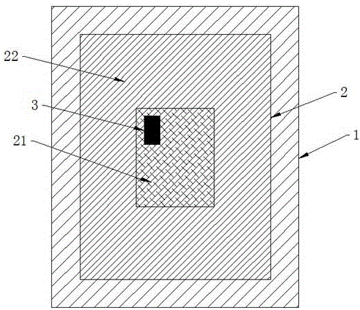
[0029] A. Make tooling 2: Prepare an aluminum-silicon plate, plate gold on the central area of ​​the upper surface of the aluminum-silicon plate, divide the upper surface of the aluminum-silicon plate into a coating area 21 and an uncoated area 22, and make a tooling;

[0030] B. Tooling 2 and workpiece 3 preheating: fix tooling 2 on heating table 1, start heating table 1 to heat the tooling to the preset temperature, place the workpiece to be pre-tinned on heating table 2, and start heating table 2 Preheat the workpiece;

[0031] C. Add solder: place the solder on the gold-plated area 21 of the frock to melt the solder;

[0032] D. Tinning: move the preheated workpiece 3 to the coating area 21 of the tooling 2, the back of the workpiece 3 is in co...


PUM

PropertyMeasurementUnit
Thicknessaaaaaaaaaa

Abstract

The invention provides a microcircuit module back side pre-soldering method which comprises the steps of (A) making a tool: preparing an aluminum silicon plate, carrying out gold plating at the center area of the upper surface of the aluminum silicon plate, dividing the upper surface of the aluminum silicon plate into a plating area and a non-plating area, and making the tool, (B) carrying out tool and workpiece preheating: fixing the tool to a heating platform 1, starting the heating platform 1 to heat the tool to a preset temperature, placing a workpiece with the need of pre-soldering to a heating platform 2, and starting the heating platform 2 to carry out preheating of the workpiece, (C) adding a solder: placing the solder to the plating area of the tool and allowing the solder to melt, (D) tinning: moving the preheated workpiece to the plating area of the tool, wherein the back side of the took is in contact with the solder and rubs the plating area, and thus the solder is uniformly coated to the back side of the workpiece, and (E) examination: moving the workpiece to the non-plating area of the tool, checking whether the tinning of the back side of the workpiece is qualified or not, and repeating the step (D) if not until the tinning of the back side of the workpiece is qualified. The invention also provides a pre-soldering heating device.

Description

technical field [0001] The invention provides a method for pre-tinning the back of a microcircuit module, which belongs to the technical field of electronic component manufacturing. The invention also provides a pre-tinning heating device. Background technique [0002] With the development of the electronics industry, microcircuit modules are widely used in various fields. Since a large number of components are assembled in the cavity of the microcircuit module, and its assembly is soldered with a solder with a low melting point, in order to enhance the reliability of the soldering, it is necessary to pre-tin the back of the original component. [0003] In the existing pre-tinning of microcircuit modules and components, most of the components are turned upside down on the heated tooling, the tin wire or solder sheet is directly melted on the back of the components, and then the solder is smoothed with a cotton swab. This method The operation is simple, the cost is low, t...

Claims


Application Information

Patent Timeline
IPC IPC(8): H05K3/34
CPCH05K3/3478
Inventor 吴诗晗彭欣杨伟
Owner ZHUZHOU TIANWEI TECH CO LTD
Why Eureka
Try Eureka