
A three-level bidirectional charging and discharging circuit

A charge-discharge circuit, three-level technology, applied to battery circuit devices, circuit devices, collectors, etc., can solve problems such as unfavorable system stability, small adjustment range of charge-discharge voltage, large single-phase output ripple, etc., to achieve High engineering application value, realizing the frequency multiplication function of the inductor current, and reducing the effect of ripple

Active Publication Date: 2019-04-05
博格华纳新能源(襄阳)有限公司
View PDF5 Cites 0 Cited by
  • Summary
  • Abstract
  • Description
  • Claims
  • Application Information

AI Technical Summary

Problems solved by technology

However, compared with the single-phase output ripple, this traditional two-level bidirectional charging and discharging circuit is still relatively large, and the charging and discharging voltage adjustment range is relatively small, which is not conducive to the stability of the system.

Method used


Image

  • A three-level bidirectional charging and discharging circuit
  • A three-level bidirectional charging and discharging circuit

Examples


Embodiment approach

[0066] In a preferred embodiment of the present invention, the filter circuit includes:

[0067] A first inductor L1, connected to the first reference node V r1 and a third reference node V r3 between;

[0068] A second inductor L2, connected to the third reference node V r3 and battery voltage terminal B1;

[0069] A first filter capacitor C3, connected to the third reference node V r3 and battery voltage terminal B1.

[0070] The first inductor L1 is connected to V r1 and V r3 Between, the second inductor L2 is connected to V r3 Between and battery B1, the first filter capacitor C3 is connected to the third reference node V r3 and battery B1.

[0071] In a preferred embodiment of the present invention, the three-level bidirectional charging and discharging circuit further includes: an air switch S1 connected between the grid voltage terminal and the PWM rectifier PWM1 for protecting the charging and discharging circuit.

[0072] The present invention adopts a three...


PUM


Abstract

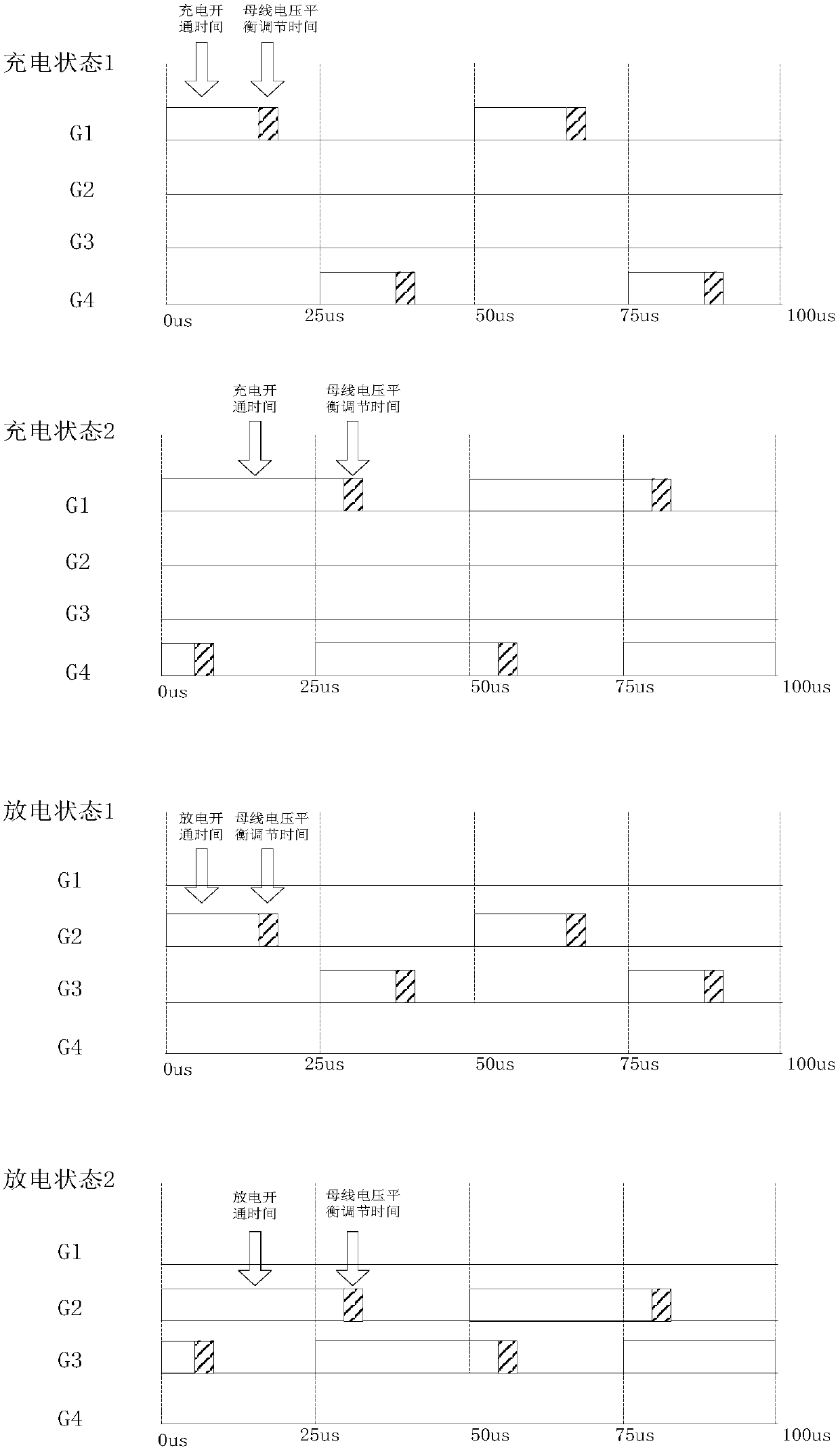
The invention relates to a charge and discharge circuit and especially relates to a three-level bidirectional charge and discharge circuit. The three-level bidirectional charge and discharge circuit comprises a power grid voltage end; a PWM rectifier comprising a first output end and a second output end, wherein a first bus capacitor and a second bus capacitor are connected in series between the first output end and the second output end; and a first charge branch, a second charge branch, a first discharge branch and a second discharge branch, wherein under a charge or discharge state, when battery voltages are higher than one half of bus voltages or lower than one half of the bus voltages, the first charge branch and the second charge branch are controllably conducted so as to adjust a balance between the bus voltages and the battery voltages. According to the invention, conduction of the charge and discharge circuit can be controllably adjusted through a control circuit, the balance between the bus voltages and the battery voltages can be adjusted, and the direction of a positive and negative bus voltage difference is controlled in a phase shift mode, more importantly, single-phase output ripples can be reduced, and an inductive current frequency multiplication function is realized.

Description

technical field [0001] The invention relates to a charging and discharging circuit, in particular to a three-level bidirectional charging and discharging circuit. Background technique [0002] The traditional two-level circuit adopts dual PWM control technology, which is composed of a PWM rectifier and an inverter, and the PWM rectifier is used to realize the bidirectional flow of energy. In addition, through the method of multi-channel parallel connection and software phase-shift control of the bus voltage, the output power of large current and low ripple can be realized. However, compared with the single-phase output ripple, this traditional two-level bidirectional charging and discharging circuit is still relatively large, and the charging and discharging voltage adjustment range is relatively small, which is not conducive to the stability of the system. Therefore, the present invention proposes a three-level bidirectional charging and discharging circuit for the above e...

Claims


Application Information

Patent Timeline
Patent Type & Authority Patents(China)
IPC IPC(8): H02J7/00H02J7/04
CPCH02J7/0068H02J7/045
Inventor 彭华良李成杰
Owner 博格华纳新能源(襄阳)有限公司
Learn More