
Real-time overtone editing circuit

A circuit and overtone technology, applied in the field of real-time overtone editing circuit, can solve the problems of undiscovered published patents and achieve fast results

Active Publication Date: 2016-07-13
TIANJIN INST OF METROLOGICAL SUPERVISION & TESTING
View PDF4 Cites 0 Cited by
  • Summary
  • Abstract
  • Description
  • Claims
  • Application Information

AI Technical Summary

Problems solved by technology

[0006] After searching, no similar published patents were found

Method used


Image

  • Real-time overtone editing circuit
  • Real-time overtone editing circuit
  • Real-time overtone editing circuit

Examples


Embodiment Construction

[0019] The present invention will be further described in detail below in conjunction with the accompanying drawings and through specific embodiments. The following embodiments are only descriptive, not restrictive, and cannot limit the protection scope of the present invention.

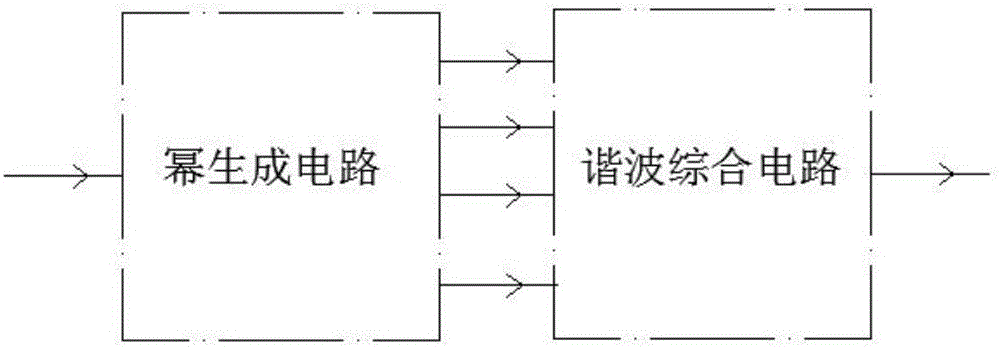
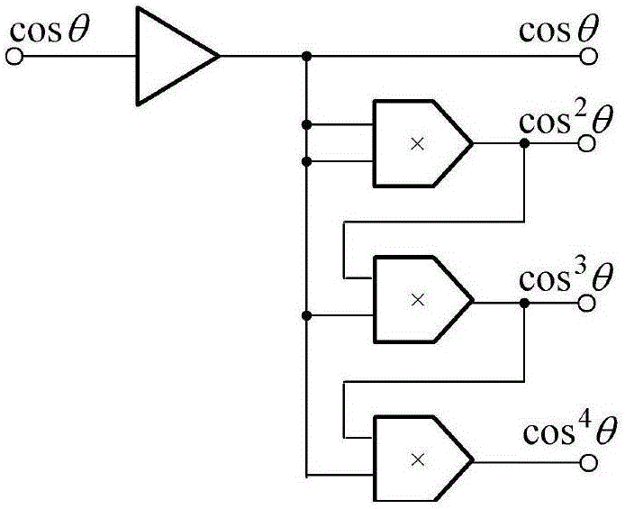
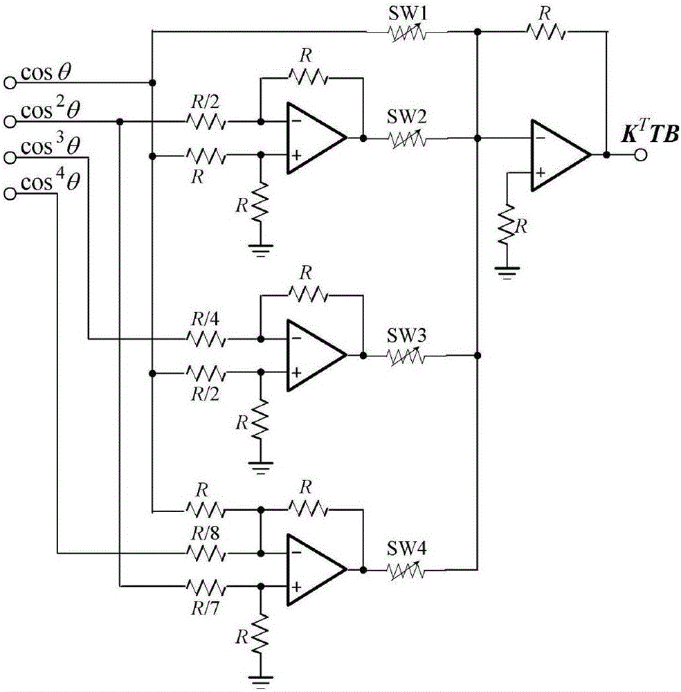
[0020] A real-time overtone editing circuit, the circuit is composed of a cascaded power generation circuit and a harmonic synthesis circuit. Complete overtone signal. The two parts of the circuit are specifically:

[0021] See the attached power generation circuit figure 1 As shown, the bus between the input terminal and the output terminal of the power generating circuit is connected with a multi-stage exponentiation circuit. The exponentiation circuit shown in this embodiment adopts a three-stage analog multiplier, and two stages of the first-stage analog multiplier The input terminals are all connected to the busbar, and then the two input terminals of the analog multiplier of each stage are re...


PUM


Abstract

The invention relates to a real-time audio signal editing method and circuit.The circuit consists of a power generating circuit and an overtone synthesis circuit, wherein an audio signal is input to the power generating circuit, the output end of the power generating circuit is connected with the input end of the overtone synthesis circuit, and the overtone synthesis circuit outputs a processed overtone signal.The real-time overtone editing circuit adopts an analog circuit to achieve a frequency multiplication function, utilizes the advantages of high speed of the analog circuit, can operate any audio input signal to obtain higher-harmonic signals.

Description

technical field [0001] The invention belongs to the field of audio signal editing, in particular to a real-time overtone editing circuit. Background technique [0002] The frequency of the audio signal is (20-20000) Hz, and the span reaches 3 orders of magnitude. If overtones are taken into account, the upper frequency limit reaches at least 100kHz. Subtle changes in the frequency spectrum of an audio signal will cause a different sense of hearing. Therefore, the processing of audio signals has long been an indispensable means in electronic audio production and performance summarization. [0003] Overtone is the superposition of fundamental frequency and double frequency signal. The fundamental frequency determines the tone, and the octave determines the timbre, so the overtone has a timbre. Electronic music production or live performance often require specific timbres, and various effects can achieve rich timbres. But the timbre obtained by the effector is fixed. For ...

Claims


Application Information

Patent Timeline
Patent Type & Authority Applications(China)
IPC IPC(8): H04R3/00
CPCH04R3/00H04R2430/00
Inventor 郭景涛张一萌王强
Owner TIANJIN INST OF METROLOGICAL SUPERVISION & TESTING
Learn More