Arc-extinguishing device of control and protection switch

A technology of arc extinguishing device and protection switch, which is applied to electric switches, electrical components, circuits, etc., and can solve the problems of arc generation, arc impact, and large arc spraying distance.

Inactive Publication Date: 2017-02-15
RADIN ELECTRIC TECH
View PDF6 Cites 0 Cited by
  • Summary
  • Abstract
  • Description
  • Claims
  • Application Information

AI Technical Summary

Problems solved by technology

[0002] At present, the arc extinguishing devices for control and protection switches on the market generally include a base and multiple sets of arc extinguishing chambers inside the base. Both sides of the base are provided with air outlets communicating with each set of arc extinguishing chambers. The arc extinguishing chambers are composed of Composed of the left arc extinguishing chamber and the right arc extinguishing chamber, there is a contact bridge between the left arc extinguishing chamber and the right arc extinguishing chamber, the two ends of the contact bridge are provided with arc strike feet, and one end of the contact bridge extends into the left arc extinguishing chamber and the other One end extends into the right arc extinguishing chamber. There are several arc extinguishing grids in the left arc extinguishing chamber and the right arc extinguishing chamber. The arc extinguishing chamber is equipped with an arc strike plate. The arc strike plate is designed in one piece and runs through the left arc extinguish chamber and the In the right arc extinguishing chamber, this kind of phenomenon is easy to produce arc series, and the arc-leading pin is easy to burn out. Although the air outlet in the above structure can discharge the hot air, it is easy to generate arc. In addition, one end of the arc extinguishing grid is provided with multiple arc striking feet, and the other end is a flat edge. The flat edge is not conducive to the arc ignition of the arc extinguishing grid, and the arc is likely to directly hit the flat edge (the flat edge is not conducive to the guidance of the arc). , so that the arc striking effect of the arc extinguisher is poor

Method used


Image

  • Arc-extinguishing device of control and protection switch
  • Arc-extinguishing device of control and protection switch
  • Arc-extinguishing device of control and protection switch

Examples


Embodiment Construction

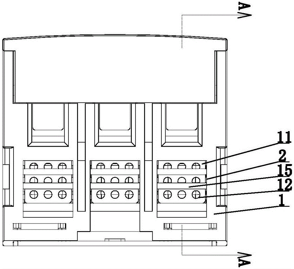
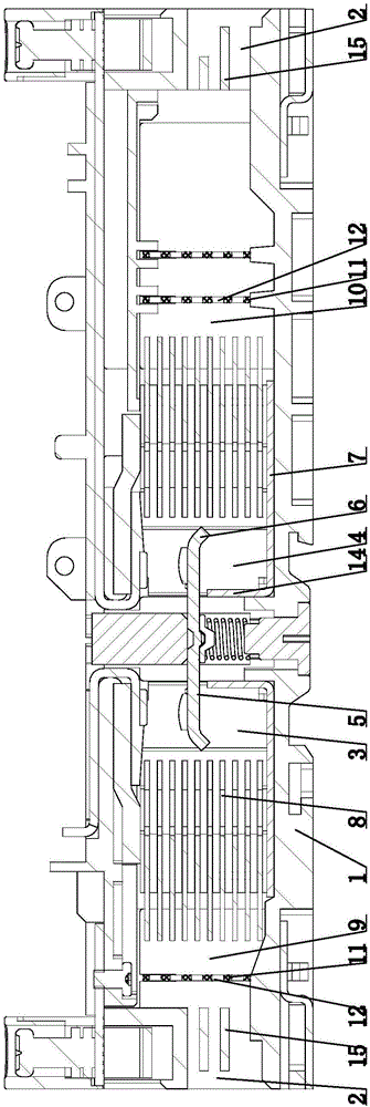
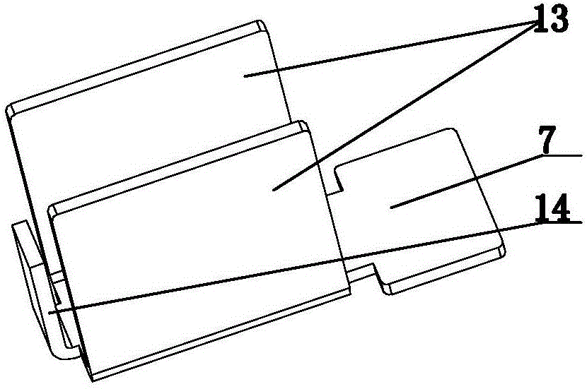
[0016] Reference figure 1 , figure 2 , image 3 with Figure 4 As shown, the arc extinguishing device for the control and protection switch provided by the present invention includes a base 1 and multiple groups of arc extinguishing chambers arranged in the base 1. Both sides of the base 1 are provided with vent holes 2 communicating with each group of arc extinguishing chambers. The arc extinguishing chamber is composed of the left arc extinguishing chamber 3 and the right arc extinguishing chamber 4. A contact bridge 5 is provided between the left arc extinguishing chamber 3 and the right arc extinguishing chamber 4, and arcing feet 6 are provided at both ends of the contact bridge 5, and One end of the contact bridge 5 extends into the left arc extinguishing chamber 3 and the other end extends into the right arc extinguishing chamber 4. Both the left arc extinguishing chamber 3 and the right arc extinguishing chamber 4 are provided with an arc ignition plate 7 and a number o...


PUM


Abstract

The invention discloses an arc-extinguishing device of a control and protection switch. The arc-extinguishing device comprises a pedestal and a plurality of arc-extinguishing chamber groups arranged inside the pedestal. Air outlets communicated with each arc-extinguishing chamber group are formed in the two sides of the pedestal. The arc-extinguishing chambers are formed by left arc-extinguishing chambers and right arc-extinguishing chambers; contact bridges are arranged between the left arc-extinguishing chambers and the right arc-extinguishing chambers; arc pins are arranged at the two ends of the contact bridges; and one end of each contact bridge extends into one left arc-extinguishing chamber and the other end extends into one right arc-extinguishing chamber. The arc-extinguishing device is characterized in that art striking plates and a plurality of arc-extinguishing grid plates are arranged in all left arc-extinguishing chambers and the right arc-extinguishing chambers; first buffer chambers for communication of the air outlets and the left arc-extinguishing chambers are arranged at the left sides of the left arc-extinguishing chambers; and second buffer chambers for communication of the air outlets and the right arc-extinguishing chambers are arranged at the right sides of the right arc-extinguishing chambers. Metallic separation boards are arranged in the first buffer chambers and the second buffer chambers; and a plurality of through holes are formed in the metallic separation boards. According to the invention, frequent arc extending can be avoided; the arc can be weakened or eliminated; burning of the arc pins is prevented; and the arc striking effect of the arc-extinguishing grid plates is good.

Description

Technical field [0001] The invention relates to an arc extinguishing device for a control and protection switch. Background technique [0002] At present, the arc extinguishing devices for control and protection switches provided on the market generally include a base and multiple groups of arc extinguishing chambers arranged in the base. Both sides of the base are provided with vent holes connected to each group of arc extinguishing chambers. The left arc extinguishing chamber and the right arc extinguishing chamber are composed of a contact bridge between the left arc extinguishing chamber and the right arc extinguishing chamber. One end extends into the right arc extinguishing chamber. Both the left arc extinguishing chamber and the right arc extinguishing chamber are equipped with several arc extinguishing grids. The arc extinguishing chamber is equipped with an arc ignition plate. The arc ignition plate is an integrated design and runs through the left arc extinguishing cham...

Claims


Application Information

Patent Timeline
IPC IPC(8): H01H9/34
CPCH01H9/346
Inventor 张彭春刘超儒杨辉吴杰江维强李里
Owner RADIN ELECTRIC TECH
Why Eureka
Try Eureka