
Chain network external fault location extension method

A technology of chain network and out-of-area faults, which is applied in the direction of fault location, measuring electricity, and measuring devices, can solve the problems of difficulty in fault location and high operating costs of the double-terminal traveling wave method, and achieve the goal of overcoming the difficulty of fault location and measuring The results are accurate and reliable, and the effect of reducing construction costs

Inactive Publication Date: 2017-02-15
KUNMING UNIV OF SCI & TECH
View PDF6 Cites 1 Cited by
  • Summary
  • Abstract
  • Description
  • Claims
  • Application Information

AI Technical Summary

Problems solved by technology

[0004] The technical problem to be solved by the present invention is to propose a chain network fault distance measurement and continuation method. A traveling wave distance measurement device is installed at one end of the chain network to collect the fault initial fault when the lower-level line is faulty at the measurement end. Traveling wave and reflected wave at fault point, fault location based on traveling wave ranging theory and empirical wave velocity, overcomes the disadvantages of difficulty in fault location of unmonitored lines of chain transmission lines and high operating cost of double-ended traveling wave method

Method used


Image

  • Chain network external fault location extension method
  • Chain network external fault location extension method
  • Chain network external fault location extension method

Examples


Embodiment 1

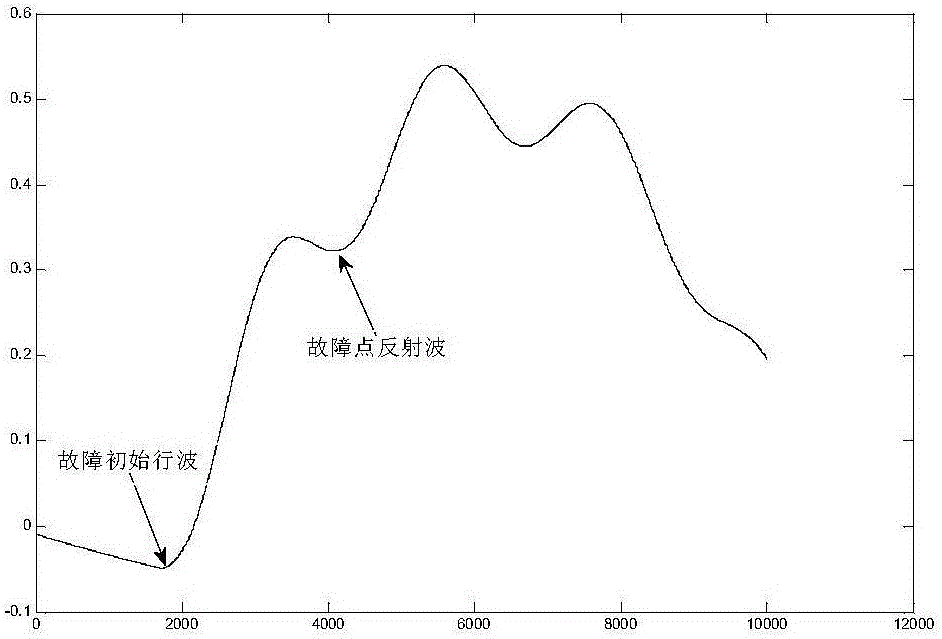
[0033] Such as figure 1 Shown is a chain network composed of three substations M, N, P, and the lengths of each line are: the length of the healthy line MN is l=10km, and the length of the faulty line NP=90km. Assume that a phase-A ground fault occurs 55km away from the N-terminal of the bus on line NP, the initial fault angle is 120°, the transition resistance is 10Ω, and the sampling rate is 1MHz.

[0034] according to figure 2 The time corresponding to the current traveling wave diagram to find out the fault wave head is t 1 = 0.213867s,t 2 =0.216270s; find the fault wave head time difference Δt=t 2 -t 1 =0.002403s, v is taken as the empirical wave velocity, and its size is 2.98×10 8 m / s; finally use the formula (3) to calculate the fault distance l f =l-v·Δt / 2=54.2km, meeting the requirements within the error range.

Embodiment 2

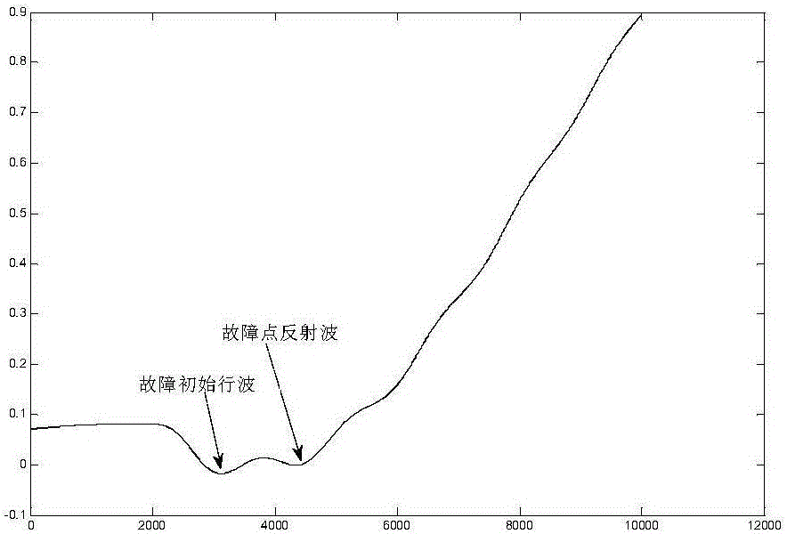
[0036] Such as figure 1Shown is a chain network composed of three substations M, N, P, and the lengths of each line are: the length of the healthy line MN is l=10km, and the length of the faulty line NP=90km. Assume that a phase A ground fault occurs at a distance of 20km from the N terminal of the busbar on the line NP, the initial fault angle is 90°, the transition resistance is 10Ω, and the sampling rate is 1MHz.

[0037] According to the current traveling wave diagram shown in Figure 3, find out the time corresponding to the fault wave head as t 1 = 0.208068s,t 2 =0.209440s; find the fault wave head time difference Δt=t 1 -t 2 =0.000668s, v is taken as the empirical wave velocity, and its size is 2.98×10 8 m / s; finally use the formula (2) to calculate the fault distance l f =v·Δt / 2=20.44km, meeting the requirements within the error range.


PUM


Abstract

The invention relates to a chain network external fault location extension method, belonging to the technical field of power system relay protection. The method includes that in the chain network consisting of three ends, a line MN is a cable, a line NP is an aerial conductor, and only a transformer station connected to a bus M is equipped with a traveling wave location device inside, when the power transmission line NP, which is not monitored by the traveling wave location device, has faults, the current traveling wave of the measuring end TA1, close to the bus M side, in a healthy line MN is acquired by the traveling wave location device, the time for the transmission of the initial travelling wave to the TA1 through the healthy line MN and the time for the transmission of the fault point reflection wave to the TA1 through the healthy line MN are respectively recorded, and the time difference Delta t is calculated, and at the end, the fault distance lf is calculated through the combination of the location theory and empirical velocity. According to the invention, one only needs to install a detection device at one end of the chain network, so that the defects of difficult fault location of circuits that are not monitored and high running cost of a double-end travelling wave method are overcome and the construction cost is reduced.

Description

technical field [0001] The invention relates to a method for distance measurement and extension of out-of-area faults in a chain network, and belongs to the technical field of electric power system relay protection. Background technique [0002] After the transmission line fails, quickly and accurately determine the location of the line fault, which will help reduce the burden of on-site operation and maintenance personnel to patrol the line, shorten the fault repair time, reduce the loss of system power outage, and effectively ensure the stable operation of the power system. [0003] The current fault location methods mainly include fault analysis method, impedance method and traveling wave method. The traveling wave method uses the propagation time of the fault traveling wave between the busbar and the fault point to measure the fault distance. Its distance measurement accuracy is high and its application range is wide. When the line fails, the traveling wave distance mea...

Claims


Application Information

Patent Timeline
Patent Type & Authority Applications(China)
IPC IPC(8): G01R31/08
CPCG01R31/088
Inventor 束洪春沐润志卢杨陈诺
Owner KUNMING UNIV OF SCI & TECH
Learn More