
Ceiling machine and control method thereof

A control method, ceiling machine technology, applied in air flow control components, heating and ventilation control systems, heating methods, etc., can solve the problems of increasing wind flow resistance, unfavorable long-distance wind transmission, loss of air volume, etc., to improve air volume, The effect of avoiding extrusion and friction and reducing energy consumption

Active Publication Date: 2017-02-15
WUHU MATY AIR CONDITIONING EQUIP CO LTD +1
View PDF8 Cites 5 Cited by
  • Summary
  • Abstract
  • Description
  • Claims
  • Application Information

AI Technical Summary

Problems solved by technology

Due to the existence of the wind deflector, the resistance of the wind flow is increased, the air volume is lost, and it is not conducive to the long-distance transmission of the wind

Method used


Image

  • Ceiling machine and control method thereof
  • Ceiling machine and control method thereof
  • Ceiling machine and control method thereof

Examples


Embodiment Construction

[0034] The following will clearly and completely describe the technical solutions in the embodiments of the present invention with reference to the accompanying drawings in the embodiments of the present invention. Obviously, the described embodiments are only part of the embodiments of the present invention, not all of them. Based on the embodiments of the present invention, all other embodiments obtained by persons of ordinary skill in the art without creative efforts fall within the protection scope of the present invention.

[0035] It should be noted that all directional indications (such as up, down, left, right, front, back...) in the embodiments of the present invention are only used to explain the relationship between the components in a certain posture (as shown in the accompanying drawings). Relative positional relationship, movement conditions, etc., if the specific posture changes, the directional indication will also change accordingly.

[0036] In addition, the ...


PUM


Abstract

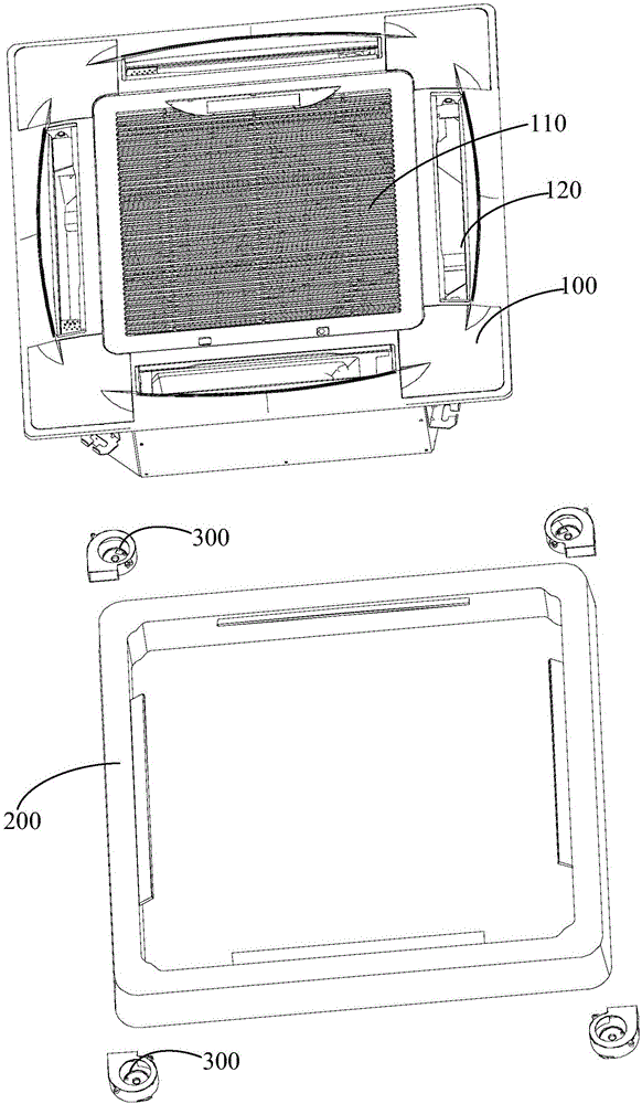
The invention discloses a ceiling machine and a control method thereof. The ceiling machine comprises a shell, flow guide pieces and an air flow driving device; the shell is provided with a main air inlet, a plurality of main air outlets and a main air flue used for communicating the main air inlet and the main air outlets; each flow guide piece comprises a plurality of air suction parts and a flow guide part, the flow guide part is detachably connected with the shell, the air suction parts extend to the main air outlets from the flow guide part, each flow guide piece is provided with an auxiliary air inlet, auxiliary air outlets and an auxiliary air flue for communicating the auxiliary air inlet and auxiliary air outlets, and the auxiliary air inlet is communicated with the main air flue; and the air flow driving device is used for driving air flow to enter the auxiliary air flue from the auxiliary air inlet. In the technical scheme, through the arrangement of an auxiliary air flue system, the air flow direction is changed under the effect of the air pressure, extrusion and friction between the air flow and a solid are avoided, and therefore the energy consumption of the air flow in the direction changing process is greatly reduced; and in this way, the air volume is better improved, the air speed is kept, and a user can conveniently send air flow to a far designated spot.

Description

technical field [0001] The invention relates to the technical field of air conditioning, in particular to a ceiling machine and a control method thereof. Background technique [0002] In order to send the wind to the area designated by the user accurately, the existing air conditioners are all provided with air deflectors. The wind deflector is set at an angle between its surface and the flow direction of the wind to forcibly change the flow direction of the wind. Due to the existence of the wind deflector, the resistance of the wind flow is increased, the air volume is lost, and it is not conducive to the long-distance transmission of the wind. Contents of the invention [0003] The main purpose of the present invention is to provide a ceiling fan, which aims to reduce the resistance of wind flow, so as to increase the wind speed and air volume of the air supply of the air conditioner. [0004] In order to achieve the above object, the ceiling machine proposed by the pr...

Claims


Application Information

Patent Timeline
IPC IPC(8): F24F7/06F24F13/14F24F11/00
CPCF24F7/06F24F11/0001F24F11/70F24F11/79F24F13/1426F24F2013/1433F24F2011/0005
Inventor 刘阳叶海林
Owner WUHU MATY AIR CONDITIONING EQUIP CO LTD
Learn More