Post-fracture flow-back tracking detecting method for horizontal well

A detection method and horizontal well technology, which is applied in the direction of earthwork drilling, wellbore/well components, production fluid, etc. It can solve the problem of inability to determine whether the liquid at target point B returns to the wellbore or not, and whether the tracer concentration is accurate Filling, insufficient stability and reliability, etc., to achieve the effect of stable detection results, strong practicability, and reliable filling

Inactive Publication Date: 2017-02-15
CHINA PETROLEUM & CHEM CORP +1
View PDF3 Cites 10 Cited by
  • Summary
  • Abstract
  • Description
  • Claims
  • Application Information

AI Technical Summary

Problems solved by technology

However, due to the particularity of the well conditions and the existing multi-stage staged fracturing technology measures for horizontal wells, it is impossible to simply follow the tracer technology of vertical wells for post-fracture evaluation, so it is impossible to determine the B target liquid of horizontal wells Whether the wellbore is flowed back, whether the wellbore is unblocked, etc., have brought a series of technical problems
In addition, the tracers used in the existing isotope and trace substance tracer technology require specific personnel to detect and release them, and the cost is high, while the cheap inorganic salt tracers or fluorescent dyes cannot be used due to the lack of injection and delivery technology. Realize the precise injection of the tracer concentration in the fracturing fluid, which leads to a large technical error in the post-fracture evaluation based on this, which is not stable and reliable enough

Method used


Image

  • Post-fracture flow-back tracking detecting method for horizontal well
  • Post-fracture flow-back tracking detecting method for horizontal well
  • Post-fracture flow-back tracking detecting method for horizontal well

Examples


Embodiment Construction

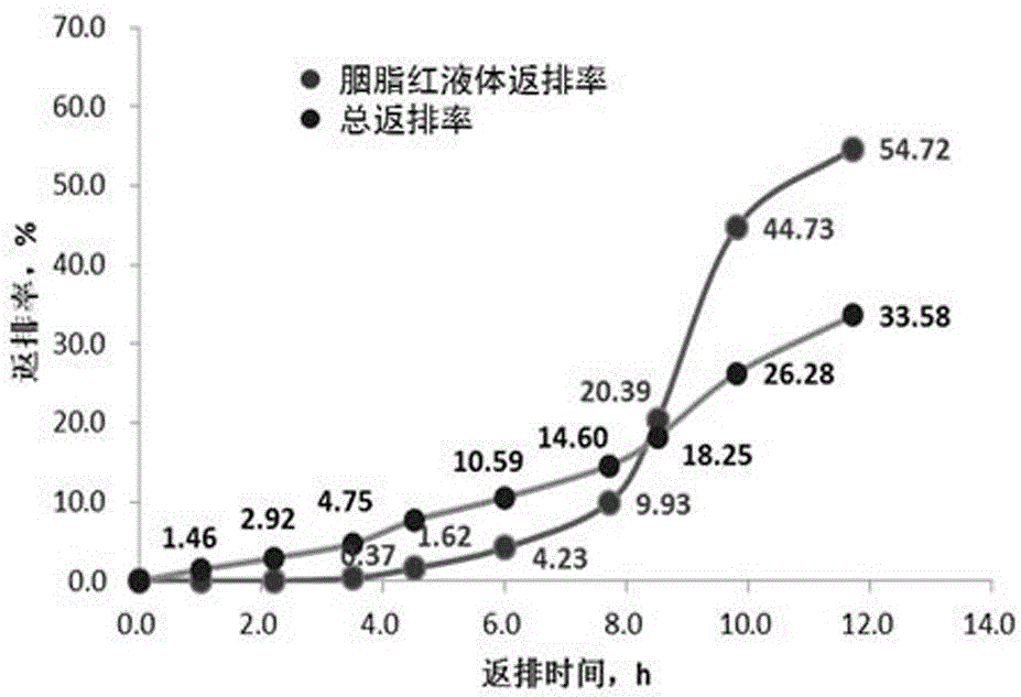
[0034] The present invention is a flowback tracing detection method after fracturing of a horizontal well, which comprises the following sequential steps:

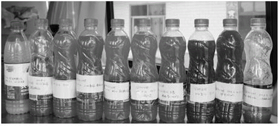
[0035] Step 1. Adding a tracer in the fracturing fluid required for construction, the tracer is a carmine tracer, so as to obtain the tracer fracturing fluid; the filling operation includes the following specific steps:

[0036] 1). According to the designed carmine concentration and tracer fracturing fluid volume, calculate the required carmine weight according to the following formula: W=C x ×V 1 ; In the formula, W is carmine weight; C x is the carmine concentration; V 1 is the tracer fracturing fluid volume;

[0037] 2). According to the tracer fracturing fluid volume and the designed construction displacement, the pumping time of the tracer fracturing fluid is calculated according to the following formula: T=V 1 / Q 1 ; where T is the pumping time of tracer fracturing fluid; Q 1 is the construction displacement; ...


PUM


Abstract

The invention discloses a post-fracture flow-back tracking detecting method for a horizontal well. The post-fracture flow-back tracking detecting method comprises the following steps: step 1, preparing a tracking fracturing fluid; step 2, carrying out fracturing and flow-back test on the tracking fracturing fluid in a straight well, recording fracturing construction parameters and flow-back parameters, and sampling a tracking flow-back liquid according to certain time interval, separately detecting tacking concentration, acquired in different time periods, in each sample, and obtaining datum data that tracking concentration changes along with time in the tracking flow-back liquid; and step 3, adopting the tracking fracturing liquid with the same tracking concentration in the step 2 to carry out fracturing construction on the horizontal well, recording the construction parameters and the flow-back parameters and sampling the tracking flow-back liquid according to certain interval time; respectively detecting tracking concentration, acquired in different time periods, in each sample, and calculating to obtain practical flow-back amount of the tracking fracturing liquid in an existing time period of the detected sample; and calculating to obtain a flow-back rate, reversed out by the horizontal well in the existing time period, at a tracing stage of the detected sample.

Description

technical field [0001] The invention relates to post-fracture evaluation technology of oil and gas wells, in particular to a flowback trace detection method after horizontal well fracturing. Background technique [0002] As an important technical measure to increase reserves and production of oil and gas wells, fracturing technology is playing an increasingly important role in the exploration and development of oil and gas fields, and the fracturing effect depends to a large extent on the knowledge and understanding of formation conditions. How to recognize and understand formation conditions requires post-fracture evaluation of oil and gas wells. [0003] At present, the post-fracture evaluation of vertical wells is mainly realized through tracer technology. However, due to the particularity of the well conditions and the existing multi-stage staged fracturing technology measures for horizontal wells, it is impossible to simply follow the tracer technology of vertical well...

Claims


Application Information

Patent Timeline
Patent Type & Authority Applications(China)
IPC IPC(8): E21B43/26E21B49/08
CPCE21B43/26E21B49/088
Inventor 黄禹忠刁素王世泽林立世栗铁峰刘琦王兴文尹琅刘斌宋燕高
Owner CHINA PETROLEUM & CHEM CORP
Why Eureka
Try Eureka