
Automatic conveying device for oil pipe rod applied to workover treatment and conveying method of automatic conveying device

A technology of automatic conveying device and conveying device, which is applied to drill pipes, drill pipes, casings, etc., can solve the problems of no thread protection device, large force on the pipe rod grab arm, and damage to the tubing rod thread, so as to reduce labor costs. The effect of handling, saving resources and reducing damage

Active Publication Date: 2017-02-15
SHENYANG AEROSPACE XINLE
View PDF9 Cites 4 Cited by
  • Summary
  • Abstract
  • Description
  • Claims
  • Application Information

AI Technical Summary

Problems solved by technology

[0004] 1. In the existing oil field transportation device, when discharging the oil pipe rod, one person needs to pull the oil pipe rod and one person to discharge the oil pipe rod, which is not only labor-intensive, has many safety hazards, but also takes time and effort;
[0005] 2. In the existing oil field transportation device, the transportation of the oil pipe rod is completed by the mechanism of grabbing the pipe rod
The maximum weight of the tubing rod reaches 140kg. The tubing rod is directly thrown by the grabbing mechanism, and the contact between the grabbing arm of the tubing rod and the grabbing hook is subjected to a large force, causing serious damage to the equipment;
[0006] 3. The existing oilfield conveying device has no thread protection device, and the threaded part of the oil pipe rod is damaged

Method used


Image

  • Automatic conveying device for oil pipe rod applied to workover treatment and conveying method of automatic conveying device
  • Automatic conveying device for oil pipe rod applied to workover treatment and conveying method of automatic conveying device
  • Automatic conveying device for oil pipe rod applied to workover treatment and conveying method of automatic conveying device

Examples


Embodiment Construction

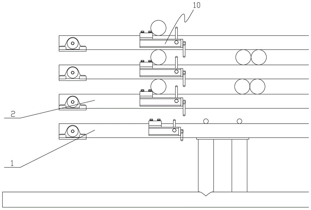
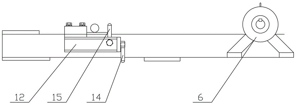
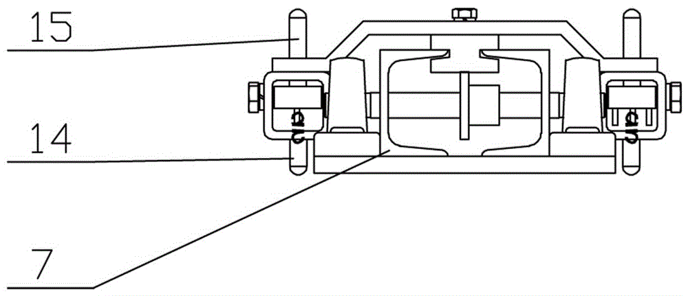
[0042] Such as Figure 1 to Figure 3 As shown, an automatic delivery device for tubing rods in workover operations, the delivery device is composed of 2 to 4 groups of parallel pipe bridges, the ends of the pipe bridges are connected to the lifting mechanism 20, and the pipe bridges are composed of four layers of spacers. It is characterized in that: at least two groups of pipe bridges are provided with a motor 6 at the end of each spacer, the spacer is connected to the pushing device 10 through a slideway 7, and a connecting plate 12 with a boss is provided above the pushing device 10, The connection plate 12 is connected with the motor 6 through a transmission device; the two ends of the connection plate 12 are respectively provided with upwardly protruding pipe-taking stop pins 15, and the pipe-taking stop pins 15 are limited by elastic devices to rotate only toward the direction of the connecting plate boss ; The end of the moving direction of the push-out device 10 is pro...


PUM


Abstract

The invention relates to an automatic conveying device for an oil pipe rod applied to workover treatment. The automatic conveying device consists of 2-4 groups of pipe bridges which are arranged in parallel; the end parts of the pipe bridges are together connected with a lifting mechanism; each pipe bridge consists of four layers of isolating pipes; the end part of each isolating pipe of at least two groups of pipe bridges is provided with a motor; each isolating pipe is connected with a push-picking device through a slide way; a connecting plate provided with a lug boss is arranged above the corresponding push-picking device and is connected with the corresponding motor through a transmission device; the two ends of each connecting plate are each provided with a pipe picking retaining pin extending out upwards; each pipe picking retaining pin is limited to rotate only towards the direction of the lug boss of the corresponding connecting plate by virtue of an elastic device; the end part, in the moving direction, of each push-picking device is provided with a pipe pushing retaining pin which is capable of rotating up and down. By adopting mechanical automatic oil pipe rod discharging equipment, the automatic conveying device provided by the invention is high in efficiency, high in quality and capable of alleviating the labor intensity.

Description

technical field [0001] The invention relates to an automatic oil pipe rod conveying device for well workover operations, which belongs to the field of mechanized oil rod conveying. Background technique [0002] With the rapid development of economy and technology, mechanical automation has also achieved rapid development. The transportation of oil pipes or oil rods in the existing oil well workover mainly relies on manual work, which has low work efficiency, high labor intensity and certain danger. [0003] For the oilfield transportation device, the existing mechanism mainly has the following problems: [0004] 1. In the existing oil field transportation device, when discharging the oil pipe rod, one person needs to pull the oil pipe rod and one person to discharge the oil pipe rod, which is not only labor-intensive, has many safety hazards, but also takes time and effort; [0005] 2. In the existing oil field conveying device, the conveying of the oil pipe rod is complet...

Claims


Application Information

Patent Timeline
IPC IPC(8): E21B19/15E21B19/14
CPCE21B19/14E21B19/15
Inventor 姜影张东雪李永成罗昕张环宇李勇于海宁王祉涵
Owner SHENYANG AEROSPACE XINLE
Learn More