Slip form mould for road shoulder forming
A technology of mold and road shoulder, applied in the field of road shoulder forming slip mold, can solve the problems of irregular function of slip mold, labor-intensive road shoulder forming, low degree of automation, etc., to reduce construction cost, reduce labor, and achieve high degree of automation Effect
- Summary
- Abstract
- Description
- Claims
- Application Information
AI Technical Summary
Problems solved by technology
Method used
Image
Examples
Embodiment 1
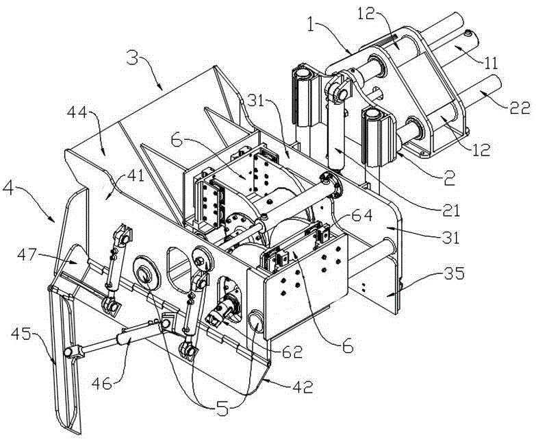
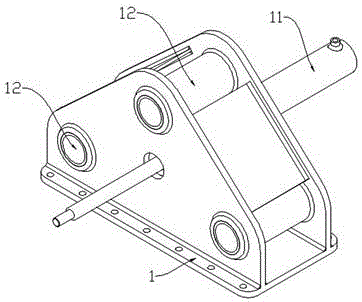
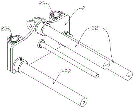
[0049] refer to Figure 1 to Figure 7 , the road shoulder forming slip form mold of the present embodiment includes a fixed seat 1, a general adjustment plate 2 connected to the fixed seat 1 and arranged vertically, and a mold connected to the general adjustment plate 2, and the mold includes two left and right mold units 3, 4;
[0050] Described left mold unit 3 comprises the left side plate 31 that is arranged vertically and the left guide plate 34 that is arranged on the front end of left side plate 31, and described right mold unit 4 includes the right side plate 41 that is arranged vertically and is arranged on the right side plate 41 front end and the right guide plate 44 that is arranged correspondingly with left guide plate 34;
[0051] The left and right mold units 3, 4 are slidably connected by a width adjustment unit 5 to move away from or approach each other in the horizontal direction. The width adjustment unit 5 includes a set of width adjustment cylinders 51 an...
Embodiment 2
[0061] refer to Figure 8 and Figure 9 The main difference between this embodiment and the above-mentioned embodiment 1 is that: the motor 62 of the left mold unit 3 in this embodiment is preferably connected to the support 621 arranged above the tamper 61 through a dovetail groove, and the left mold unit The motor 62 of the unit 3 and the tamper 61 are connected through a belt drive, so that the minimum width of the road shoulder can be further realized by such a design. The motor 62 of the right mold unit 4 is the same as that of Embodiment 1, that is, it is directly connected to its tamper 61 .
Embodiment 3
[0063] refer to Figure 10 to Figure 16 , the main difference between this embodiment and the above-mentioned embodiment 2 is: First, the tamping unit 6 in the present embodiment removes the guide rail 64, that is, the tamping device, so that the structure of the entire sliding form mold is more compact, and its total weight can be lightened, so that it can be directly The compacting function is realized by the general adjusting plate 2; secondly, the damping block 63 of the left mold unit 3 is evenly distributed on the side of the tamper 61 close to the left guide plate 34, and the damping block of the right mold unit 4 63 are evenly distributed on the front and back sides of its tamp 61, that is, two are evenly distributed on each side, so as to improve the damping effect.
PUM
 Abstract
Description
Claims
Application Information
 - R&D
- Intellectual Property
- Life Sciences
- Materials
- Tech Scout
- Unparalleled Data Quality
- Higher Quality Content
- 60% Fewer Hallucinations
Browse by: Latest US Patents, China's latest patents, Technical Efficacy Thesaurus, Application Domain, Technology Topic, Popular Technical Reports.
© 2025 PatSnap. All rights reserved.Legal|Privacy policy|Modern Slavery Act Transparency Statement|Sitemap|About US| Contact US: help@patsnap.com


