
Mounting frame of elevator landing door

A technology of elevator floor and installation frame, which is applied in the direction of elevators, transportation and packaging in buildings, which can solve the problems of high installation accuracy, poor operability, inconvenient installation and debugging of landing door devices and door leaves, etc., and reduce construction costs. Time-consuming, convenient installation and debugging, and the effect of improving installation efficiency

Inactive Publication Date: 2017-02-15
钟立朋
View PDF5 Cites 2 Cited by
  • Summary
  • Abstract
  • Description
  • Claims
  • Application Information

AI Technical Summary

Problems solved by technology

When the installation frame of the above-mentioned structure is used in the elevator landing door system, its installation accuracy is high, and the actual operability is poor; Connect with the left and right columns fixed on the wall of the building floor, or directly fix the landing door device on the installation structure on the wall of the floor through the connecting plate on it
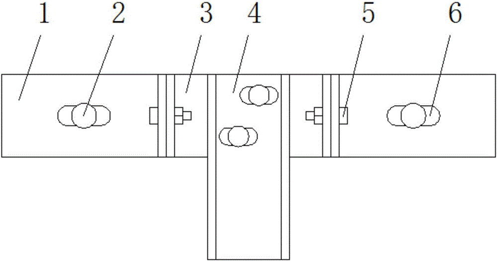
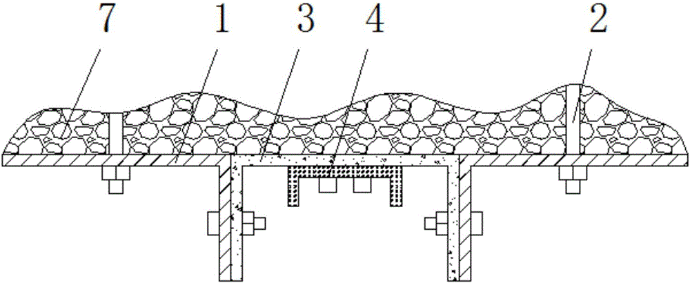
The disadvantage of these installation methods is that after the landing door device is installed on the column or the wall, its position is basically fixed, and there is almost no or only a small range of allowable debugging and / or adjustment, which greatly affects the landing door device and the door leaf. The correct installation and debugging have brought great inconvenience

Method used


Image

  • Mounting frame of elevator landing door
  • Mounting frame of elevator landing door

Examples


Embodiment Construction

[0013] The following will clearly and completely describe the technical solutions in the embodiments of the present invention with reference to the accompanying drawings in the embodiments of the present invention. Obviously, the described embodiments are only some, not all, embodiments of the present invention. Based on the embodiments of the present invention, all other embodiments obtained by persons of ordinary skill in the art without making creative efforts belong to the protection scope of the present invention.

[0014] see Figure 1-2 , an embodiment provided by the present invention: a mounting frame for an elevator landing door, including a grooved landing door connector 3, a wall connector 1 and a landing door connector 4, and the grooved landing door connector 3 is installed on both sides There is a wall connector 1, and a bolt hole 6 is arranged on the wall connector 1, and a landing door connector 4 is installed on the front part of the slot-type landing door co...


PUM


Abstract

The invention discloses a mounting frame of an elevator landing door. The mounting frame comprises a trough type landing door connecting part, wall face connecting parts and a landing door connecting part. The wall face connecting parts are mounted on the two sides of the trough type landing door connecting part. Bolt holes are formed in the wall face connecting parts. The landing door connecting part is mounted on the front portion of the trough type landing door connecting part. Bolt holes are formed in the landing door connecting part. The landing door connecting part is provided with the two bolt holes. The landing door connecting part is connected with the trough type landing door connecting part through a fixing bolt. According to the mounting frame, the trough type landing door connecting part, the wall face connecting parts and the landing door connecting part are provided with the bolt holes, the positions of the mounting frame can be allowed to be flexibly adjusted in all direction such as up, down, left, right, front and back according to actual mounting conditions, mounting and debugging are facilitated, the mounting efficiency is effectively improved, and the construction time is shortened.

Description

technical field [0001] The invention relates to the technical field of elevator landing door application equipment, in particular to a mounting frame for elevator landing doors. Background technique [0002] At present, the existing elevator landing door system generally includes the upper sill plate, the elevator door hanging plate, the elevator door linkage device, the elevator door opening and closing device and the elevator door panel, and the upper sill plate is often fixed by the elevator landing door installation frame. on the door frame. And commonly used elevator landing door installation frame is the bent plate of an L-shaped structure, all offers waist-shaped hole on the transverse part and the vertical part of bent plate. Considering that the mounting frame of the above structure is an integral structure, there is no adjustment gap between the horizontal part and the vertical part. When the installation frame of the above-mentioned structure is used in the elev...

Claims


Application Information

Patent Timeline
Patent Type & Authority Applications(China)
IPC IPC(8): B66B13/30
CPCB66B13/30
Inventor 钟立朋
Owner 钟立朋
Learn More