
Flyover Circulation Lift

A lift and flyover technology, applied in the field of elevators, can solve the problems of slow walking speed, inconvenience, and inability to pass, and achieve the effects of low manufacturing cost, simple structure and convenient installation.

Active Publication Date: 2019-01-11
JANGSU RIGHT HEAVY MACHINERY CO LTD
View PDF2 Cites 0 Cited by
  • Summary
  • Abstract
  • Description
  • Claims
  • Application Information

AI Technical Summary

Problems solved by technology

[0006] Compared with the elevator, the electric escalator occupies more space, and the walking speed (especially the vertical speed) is relatively very slow; but because the electric escalator operates continuously, unlike the elevator, passengers have to wait for the arrival of the car, so the electric escalator The total passenger capacity is much higher; in places where the flow of people is high and the vertical distance is not long, escalators are generally used; as for the occasions where the flow of people is small but the vertical distance is large, elevators are mostly used
[0007] However, the escalator has steps of a certain height, and passengers have to get on and off during the movement of the elevator, so baby carriages, shopping carts, wheelchairs, etc. cannot pass through, and it is very uncomfortable to pull suitcases, goods, the elderly, and children. Convenience is also dangerous, and there have been many incidents of escalator injuries in real life

Method used


Image

  • Flyover Circulation Lift
  • Flyover Circulation Lift
  • Flyover Circulation Lift

Examples


Embodiment Construction

[0052] The present invention will be further described in detail below in conjunction with the accompanying drawings and embodiments.

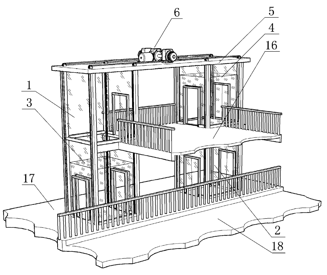
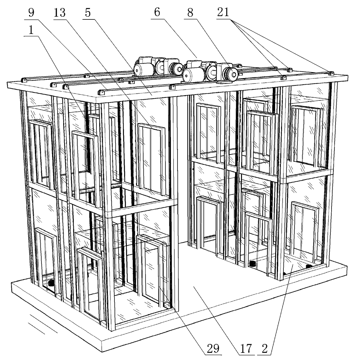
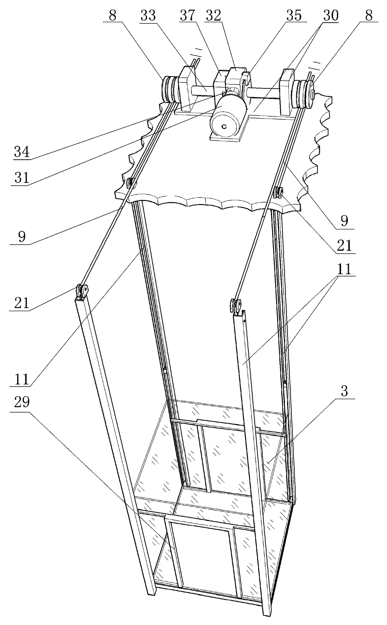
[0053] Such as Figure 1 to Figure 12 Shown: 1. Elevator shaft A, 2. Elevator shaft B, 3. Bridge compartment A, 4. Bridge compartment B, 5. Roof installation, 6. Traction system, 8. Traction wheel, 9. Traction cable , 11. Guide rail groove column, 13. Automatic landing door, 16. Overpass, 17. Sidewalk, 18. Highway, 20. Bridge box chassis, 21. Guide fixed pulley, 22. Limiting force head, 23. Pulley frame , 24. Force moving pulley, 25. Limit wheel A, 26. Limit wheel B, 28. Screw shaft, 29. Automatic door, 30. Base frame, 31. Motor, 32. Reducer, 33. Main shaft, 34. Braking device A, 35. Braking device B, 37. Speed ​​limiting device, 39. Traction hole.

[0054] Such as figure 1 , 2 , Shown in 3 and 4: the flyover circulation lift includes a flyover 16 and multiple sets of circulation lifts, the two ends of the flyover 16 are respectively provi...


PUM


Abstract

The invention discloses a circulating lifter for an overpass. The circulating lifter for the overpass comprises an overpass and a plurality of groups of circulating lifters; the two ends of the overpass are each provided with more than one group of circulating lifters; each group of circulating lifters comprise dragging systems, two same lift wells A and B and two lift cars A and B; the lower end of each lift car is provided with a lift car bottom frame; the lift wells A and B are symmetrically arranged; the top ends of the lift wells A and B are each provided with a mounting top plate and the dragging system; each lift well is provided with four straight vertical guide track groove posts; the four guide track groove posts are symmetrically arranged in two groups; the outer end of each lift car bottom frame is provided with four position-limiting force bearing heads; each position-limiting force bearing head is provided with a force bearing movable pulley and limiting wheels A and B; the two sides of each dragging system are each provided with a dragging wheel; the dragging wheels at the two sides are each provided with two dragging steel cable slots; the middle sections of four dragging steel cables are respectively intertwined on the four dragging steel cable slots on the dragging wheels at the two ends. The circulating lifter disclosed by the invention has the advantages of multiplying the utilization rate, saving energy and making the overpass become a safe and convenient barrier-free way.

Description

technical field [0001] The invention relates to an elevator, in particular to a bidirectional circulation elevator suitable for flyovers, shopping malls, stations and low-rise buildings. Background technique [0002] Elevator is a vehicle for vertically transporting pedestrians. It has a history of more than 100 years, and its technology has been perfected in all aspects; the Chinese patent application number CN201420582071.2 discloses an elevator, which is characterized in that it includes a driving device, A transmission device connected to the driving device and a carrying device; the carrying device includes a lifting link connected to the transmission device and a first bearing member and a second bearing member connected to the two free ends of the lifting link , the transmission device can move in both positive and negative directions under the action of the driving device and drive the first carrier and the second carrier to rise and fall in two opposite directions t...

Claims


Application Information

Patent Timeline
Patent Type & Authority Patents(China)
IPC IPC(8): B66B9/00
CPCB66B9/00
Inventor 吴炳发吴丹辉
Owner JANGSU RIGHT HEAVY MACHINERY CO LTD
Learn More