
Concrete block stacking machine

A technology of concrete blocks and palletizers, which is applied in the stacking of objects, unstacking of objects, transportation and packaging, etc. It can solve problems such as poor working environment, inability to proceed with mechanized and automated brick unloading, and unstable brick stacks.

Inactive Publication Date: 2017-02-15
吉林久盛生态环境科技有限公司 +1
View PDF12 Cites 6 Cited by
  • Summary
  • Abstract
  • Description
  • Claims
  • Application Information

AI Technical Summary

Problems solved by technology

However, at present, after the drying and roasting of sintered bricks, the work of unloading bricks from the kiln and stacking are all done manually. The working environment is harsh and the ambient temperature is high. Especially in the hot summer, the labor intensity is high, and more and more People are unwilling to engage in such work environment and labor-intensive work, and the cost of manual brick unloading and stacking is getting higher and higher. Therefore, fired brick products companies are eager to realize the mechanization of brick unloading, stacking, and loading.
Now some companies are trying to develop a mechanized solution for unloading bricks from the kiln car, which can solve the problem of high temperature of the kiln car and difficulty in loading and unloading bricks for brick unloaders. The method has the characteristics of a large gap between bricks. The result of unloading bricks in a whole stack is that the brick stack is unstable, and the shape of the brick stack is not suitable for storage and transportation. Manual handling cannot meet the needs of mechanized and automatic packaging of brick stacks; in addition, a series of physical and chemical changes in the firing process of sintered bricks cause deformation of brick stacks, resulting in bonding problems between bricks. It has always been the bottleneck that is difficult to break through in the realization of mechanical brick unloading, so that the mechanized and automatic brick unloading cannot continue, restricting the realization of mechanized brick unloading equipment

Method used


Image

  • Concrete block stacking machine
  • Concrete block stacking machine
  • Concrete block stacking machine

Examples


Embodiment 1

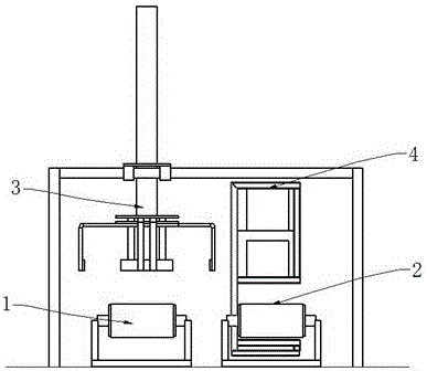
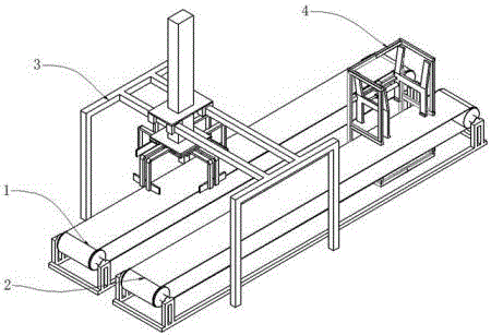
[0016] See Figure 1-5 , a concrete block palletizer, comprising: a feeding conveyor belt 1, a palletizing conveyor belt 2, a palletizer 3, and a pallet conveyor 4;

[0017] The feed conveyor belt 1 transports the formed concrete block products to the stacker;

[0018] The palletizing conveyor belt 2 is arranged on one side of the feed conveyor belt 1, and is arranged in parallel with the feed conveyor belt 1;

[0019] The palletizer 3 includes: a support frame 31, a guide rail 32, a lifting device 33, a transverse clamping frame 34, a longitudinal clamping frame 35, and a platform 36;

[0020] The support frame 31 is a door-shaped structure, and the support frame 31 is arranged above the feeding conveyor belt 1 and the stacking conveyor belt 2;

[0021] The guide rail 32 is arranged on the top of the support frame 31, and is vertically arranged with the feeding conveyor belt 1 and the stacking conveyor belt 2;

[0022] Described platform 36 is provided with slider, and sli...


PUM


Abstract

The invention discloses a concrete block stacking machine which comprises a feeding conveying belt, a stacking conveying belt, a stacking machine part and a pallet conveyer; the stacking conveying belt is arranged on one side of the feeding conveying belt, and is parallel to the feeding conveying belt; the stacking machine part comprises a supporting rack, guide rails, a lifting device, a transverse clamping rack, a longitudinal clamping rack and a platform; the supporting rack is in a portal structure, and is arranged above the feeding conveying belt and the stacking conveying belt; and the pallet conveyer comprises a rack, a left clamping plate, a right clamping plate, a synchronizing device and a driving liquid press cylinder. With the adoption of the technical scheme and measures, the conventional block stacking machine is improved; the concrete block stacking machine meets the requirements of automatic production fully; no labor is required to unload blocks from a kiln car; no manual stacking or manual loading is required; the production efficiency is improved; and the labor intensity of workers and the production cost are reduced substantially.

Description

technical field [0001] The invention belongs to the technical field of concrete block production equipment, and in particular relates to a concrete block stacker. Background technique [0002] Sintered bricks are the basic products of the wall material industry. The production of these products has the current situation of high labor intensity and harsh working environment, and the production cost is getting higher and higher. Enterprises are eager to realize the mechanization and automation of the production of sintered bricks. With the advancement of science and technology, automation equipment has been applied to many links in the production of sintered bricks. For example, the fully automatic adobe stacking machine for sintered bricks developed in recent years has realized the transformation of adobes from manual adobes to automatic mechanical adobes. Automated production has been realized before, and labor productivity has been greatly improved. However, at present, af...

Claims


Application Information

Patent Timeline
IPC IPC(8): B65G57/20B65G61/00
CPCB65G57/20B65G61/00
Inventor 李仲海赵科刘宏亮李鹏胡广龙田春树刘畅
Owner 吉林久盛生态环境科技有限公司
Learn More