Side punching die

A side punching and die technology, applied in the field of stamping die, can solve the problems of large space occupied by the wedge, increase the development cost of the die, increase the storage space of the die, etc., so as to reduce the outline size, the development cost and the storage space. , the effect of reducing the occupied space

Inactive Publication Date: 2018-03-20
ANHUI JIANGHUAI AUTOMOBILE GRP CORP LTD
View PDF5 Cites 0 Cited by
  • Summary
  • Abstract
  • Description
  • Claims
  • Application Information

AI Technical Summary

Problems solved by technology

[0004] In the prior art, the standard wedge takes up a lot of space, and it needs to increase the height of the mold and the outer dimension of the mold to realize it, which increases the mold development cost and the storage space of the mold, and the purchase cost of the standard wedge is also high.

Method used


Image

  • Side punching die
  • Side punching die
  • Side punching die

Examples


Embodiment Construction

[0035] Embodiments of the present invention are described in detail below, examples of which are shown in the drawings, wherein the same or similar reference numerals designate the same or similar elements or elements having the same or similar functions throughout. The embodiments described below by referring to the figures are exemplary only for explaining the present invention and should not be construed as limiting the present invention.

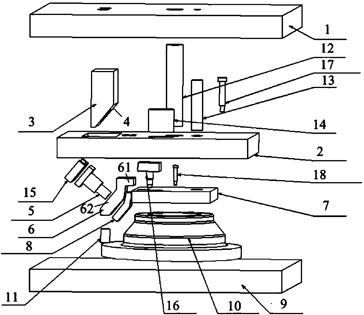
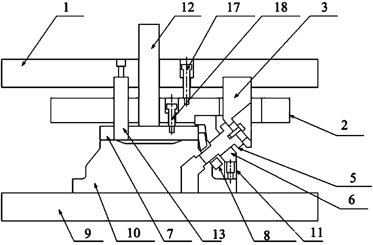
[0036] figure 2 Schematic diagram of the exploded structure of the side punching die provided by the embodiment of the present invention, image 3 A cross-sectional view of the closed state of the side punching die provided for the embodiment of the present invention, Figure 4 The cross-sectional view of the open state of the side punching die provided for the embodiment of the present invention.

[0037] Such as Figure 2 to Figure 4 As shown, the embodiment of the present invention provides a side punching die, including an upper ...


PUM


Abstract

The invention discloses a side punching die. The side punching die comprises an upper die panel, a transfer panel, a driving block, a side punching male die, a guide panel, a pressure panel, an insert, a lower die panel, a lower die insert and a cushion block, wherein the transfer panel is fixed to the bottom of the upper die panel; the upper end of the driving block is fixed to the transfer panel, and the lower end of the driving block is a bevel; the side punching male die is fixed to the bevel; the side punching male die can be driven by the driving block to punch holes in workpieces; the guide panel comprises a top panel and an inclined panel; the top panel is fixed to the transfer panel, the inclined panel is provided with a guide hole, and the guide hole is matched with the side punching male die; the pressure panel is fixed to the transfer panel; the insert is fixed to one side of the pressure panel and matched with the inclined panel; and the lower die insert is fixed to the lower die panel; the cushion block is fixed to the lower die insert and used for limiting the guide panel. The side punching die provided by the invention is used for side punching on punched panels, guiding is conducted by arranging the guide panel on the transfer panel, and the side punching die is driven through the driving block to complete side punching on the panels. Compared with the prior art, the occupied space is obviously reduced, and the development cost and storage space of the die are reduced.

Description

technical field [0001] The invention relates to stamping die technology, in particular to a side punching die. Background technique [0002] The holes on the stamping parts have different shapes and angles. The holes at a certain angle to the stamping direction need to rotate the stamping part or use a wedge to complete the punching of the hole. [0003] The solution in the prior art is to adopt the way of standard oblique wedge: as figure 1 As shown, the upper part of the standard wedge is installed on the upper formwork 1 ', and the lower part is installed on the lower formwork 2'. The punch 3' and the mold clamp 4' are installed on the upper part of the standard wedge, the positioning pin 5' is installed on the lower mold insert 6', the process part is placed on the lower mold insert 6', and the positioning pin 5' is used for positioning, pressing The material plate 7' presses the process part on the lower mold insert 6', the spring 8' provides pressure to the pressure ...

Claims


Application Information

Patent Timeline
Patent Type & Authority Patents(China)
IPC IPC(8): B21D28/34B21D37/12B21D53/88
CPCB21D28/34B21D37/12B21D53/88
Inventor 刘春雨郑薇李辉王海琳葛明雨刘春平王兴华
Owner ANHUI JIANGHUAI AUTOMOBILE GRP CORP LTD
Why Eureka
Try Eureka