Electrothermal grouping regeneration device of metal particle trap of diesel car

A technology of metal particles and regeneration device, applied in the direction of muffler device, exhaust device, electric control of exhaust treatment device, etc., can solve the problems of high process requirements, high fuel consumption, difficult particle combustion, etc., and achieve a simple regeneration control system , energy saving and emission reduction effect, the effect of simple structure

Inactive Publication Date: 2017-02-08
杨琦
View PDF0 Cites 0 Cited by
  • Summary
  • Abstract
  • Description
  • Claims
  • Application Information

AI Technical Summary

Problems solved by technology

The regeneration method generally adopts the active regeneration method of injecting diesel to burn particles. Due to the poor thermal conductivity of ceramics and the small and long honeycomb tubes, it is difficult to burn particles, and the regeneration time of the filter is also relatively long. During the regeneration process, fuel The injection cannot be stopped, so the wall-flow particle filter consumes more fuel during the regeneration process; in order to reduce fuel consumption, a catalyst is coated on the hole wall of the honeycomb ceramic to reduce the ignition temperature of the particles, and at the front end of the filter An oxidation catalyst is added to form a passive regeneration + active regeneration method. Under certain operating conditions of the car, the exhaust gas temperature of the car reaches 220°C or higher, and the particles can be automatically burned to save fuel consumption; the catalyst is made of rare It is made of metal or precious metal, and the process requirements are relatively high, so the cost is very high; the particle filter also needs a control system to select the best time for regeneration and control it, so the wall flow particle filter of honeycomb ceramic Expensive, high fuel consumption, difficult to popularize and apply in China

Method used


Image

  • Electrothermal grouping regeneration device of metal particle trap of diesel car

Examples


Embodiment Construction

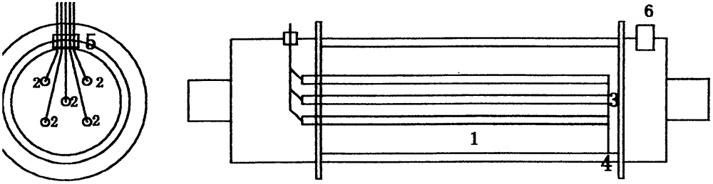
[0009] As shown in Figure 1, a grouped electrothermal regeneration device for a diesel automobile metal particle trap according to an embodiment of the present invention includes five pre-installed groups balanced in the metal filter 1 of the diesel automobile metal particle trap. A linear electric heater 2 made of multiple round core wires. Use stainless steel wire as a wire to weld one end of each group of electric heaters in parallel to form a common end 3. The other end of the stainless steel wire leads to the metal filter and welds the shell of the trap. 4. The housing of the trap is used as the negative electrode of the power supply, and the other end of the electric heater group. Each group of electric heaters is welded with a stainless steel wire to lead out the filter. Each stainless steel wire is fixed to the gas inlet assembly shell of the trap. The ceramic body terminal row posts 5 are connected in order, and one end of the terminal post extends out of the shell, and...


PUM


Abstract

The invention provides an electrothermal grouping regeneration device of a metal particle trap of a diesel car. According to the regeneration device, a plurality of groups of electric heaters are uniformly preassembled in a metal filter of the metal particle trap of the diesel car; a ceramic body wiring terminal is arranged on the shell of a gas outlet assembly shell or a gas inlet assembly of the trap; one end of the wiring terminal is connected with an electric heating wire group, and the other end of the wiring terminal extends out of the shell and is connected with a power supply controller; and a temperature sensor interface is arranged above the gas outlet assembly shell or the gas inlet assembly. According to the electrothermal grouping regeneration device of the metal particle trap of the diesel car, which is provided by the invention, power is supplied by virtue of a storage battery of the car, without energy consumption; and the regeneration device is simple in structure, low in cost, obvious in energy-saving effect, and suitable for being applied to particle traps made from a metal material, of cars, machines and ships taking diesel engines as power devices.

Description

Technical field [0001] The invention relates to a regeneration method of a metal filter, in particular to a grouped electrothermal regeneration device of a metal particle trap for diesel engines and diesel automobiles. Background technique [0002] For many years, the particle traps of diesel vehicles have always adopted a honeycomb ceramic filter, which uses the honeycomb tube wall of the honeycomb ceramic to filter and store particles. This is called a wall-flow filter. When the particles of the filter move along with the vehicle The mileage of the filter gradually accumulates, and the resistance of the filter gradually increases. It is necessary to burn the particles inside the filter to restore the initial resistance of the filter. This method is called filter regeneration. The regeneration method generally adopts the active regeneration method of injecting diesel fuel to burn the particles. Due to the poor thermal conductivity of ceramics, and the small and long honeycomb tu...

Claims


Application Information

Patent Timeline
Patent Type & Authority Applications(China)
IPC IPC(8): F01N3/027F01N9/00
CPCY02T10/40
Inventor 杨琦
Owner 杨琦
Why Eureka
Try Eureka