
Stock bin side wall ventilation unit and stock bin side wall ventilation structure formed by stock bin side wall ventilation units

A silo and ventilation hole technology, which is applied in the field of ventilation structure on the side wall of the silo, can solve the problems of blowing away materials, raising dust, environmental pollution, etc., and achieve the effect of reducing impact force and avoiding dust.

Inactive Publication Date: 2017-02-08
山西尚风抑风墙科技有限公司
View PDF7 Cites 2 Cited by
  • Summary
  • Abstract
  • Description
  • Claims
  • Application Information

AI Technical Summary

Problems solved by technology

However, if the material stacked in the silo is coal, lime and other materials that can generate dust, the external air enters the interior of the silo through the vents, which may blow the materials away, thereby generating dust, and these dusts will also be distributed to the silo through the vents. In addition, causing environmental pollution

Method used


Image

  • Stock bin side wall ventilation unit and stock bin side wall ventilation structure formed by stock bin side wall ventilation units
  • Stock bin side wall ventilation unit and stock bin side wall ventilation structure formed by stock bin side wall ventilation units
  • Stock bin side wall ventilation unit and stock bin side wall ventilation structure formed by stock bin side wall ventilation units

Examples


Embodiment Construction

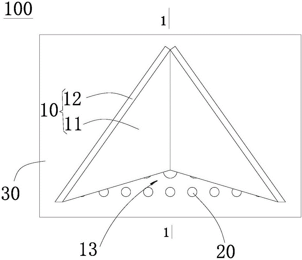
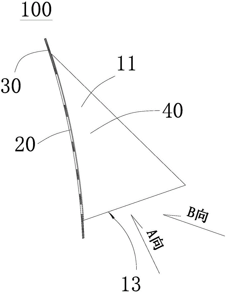
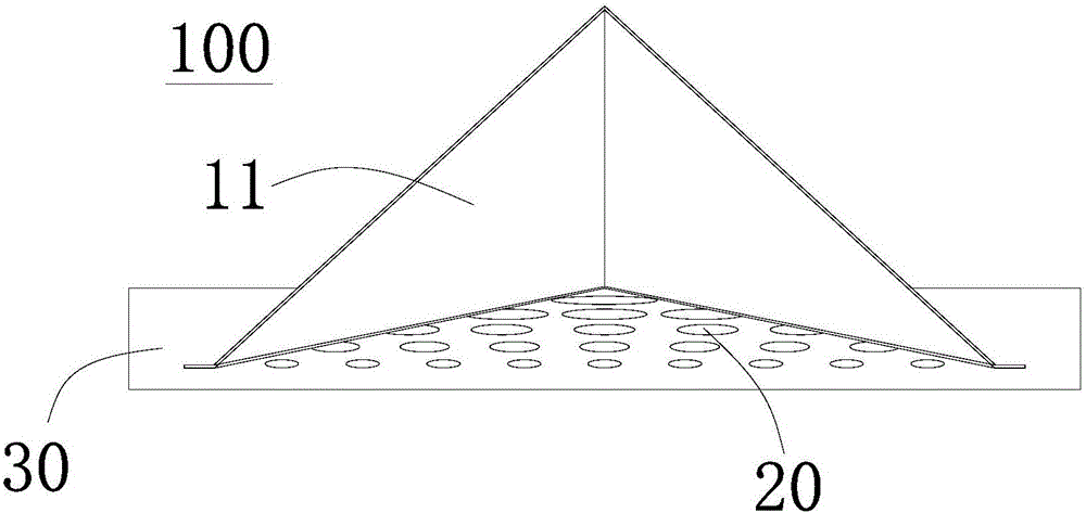
[0022] see Figure 1 to Figure 4 , a silo side wall ventilation unit 100 , including a windshield 10 , a plurality of ventilation holes 20 and a silo side wall 30 .

[0023] The windshield 10 is fixedly arranged on the outside of the side wall 30 of the silo. Preferably, the windshield 10 includes a body 11 and a fixing part 12, and the fixing part 12 is arranged between the body 11 and the The flange of the contact part of the side wall 30 of the silo, the body 11 of the windshield 10 is fixedly arranged on the outside of the side wall 30 of the silo through the fixing part 12, by setting the fixing part 12, the The contact area between the wind deflector 10 and the side wall 30 of the silo increases the fixing strength between the wind deflector 10 and the side wall 30 of the silo. The windshield 10 surrounds the outside of the ventilation hole 20 and extends to the upper part of the ventilation hole 20 , leaving an air inlet 13 on the side facing the ground to form a semi-...


PUM


Abstract

The invention discloses a stock bin side wall ventilation unit. The stock bin side wall ventilation unit comprises wind shields, a plurality of ventilation holes, and a stock bin side wall. The wind shields are fixedly arranged on the outer side of the stock bin side wall. The ventilation holes are formed in the stock bin side wall. The wind shields are arranged outside the ventilation holes in a surrounding mode and extend to the positions above the ventilation holes, an air inlet is reserved in the side facing the ground, and a semi-closed space is formed. The diameters of the ventilation holes are increased gradually in the direction from the air inlet to the interior of the semi-closed space, so that the flow directions and flow speeds of air flow entering a stock bin through the ventilation holes with different diameters and different heights are different, certain angles are formed between the air flow, part of the air flow can be counteracted, the impact force of the air flow entering the stock bin is reduced accordingly, and raising dust is avoided; and meanwhile, due to the collection effect of the oblique surfaces of the wind shields on the air flow, the pressure intensity in the semi-closed space defined by the wind shields is increased, and thus dust in the stock bin is prevented from being diffused out of the stock bin. The invention further discloses a stock bin side wall ventilation structure formed by the stock bin side wall ventilation units.

Description

technical field [0001] The invention relates to the technical field of ventilation, in particular to a ventilation structure for a side wall of a silo. Background technique [0002] At present, the silos for storing materials usually have ventilation requirements. Common vents are often set on the side walls of the silos, and shutters are arranged outside the vents to control the opening and closing of the vents. However, if the material stacked in the silo is coal, lime and other materials that can generate dust, the external air enters the interior of the silo through the vents, which may blow the materials away, thereby generating dust, and these dusts will also be distributed to the silo through the vents. In addition, it causes environmental pollution. Contents of the invention [0003] In order to overcome the deficiencies of the prior art, the object of the present invention is to provide a silo side wall ventilation unit capable of avoiding dust and a silo side wa...

Claims


Application Information

Patent Timeline
Patent Type & Authority Applications(China)
IPC IPC(8): B65D90/02
CPCB65D90/02
Inventor 张心毅
Owner 山西尚风抑风墙科技有限公司
Learn More