
Driving rear axle of mini electric vehicle

A technology for electric vehicles and rear axles, which is applied to vehicle components, control devices, transportation and packaging, etc. It can solve the problems of small internal space, insufficiently compact structure and low transmission efficiency of mini electric vehicles, and improve the internal space Insufficient, saving raw materials, and improving labor productivity

Inactive Publication Date: 2017-02-08
CHANGCHUN UNIV OF TECH
View PDF5 Cites 1 Cited by
  • Summary
  • Abstract
  • Description
  • Claims
  • Application Information

AI Technical Summary

Problems solved by technology

[0003] The existing electric vehicle drive rear axle mostly adopts the transmission structure of motor, secondary reducer and differential, the transmission chain is long, and the structure layout is not compact enough, which makes the transmission efficiency of the whole vehicle low, which is not suitable for the use of micro electric vehicles. When using a first-stage reducer, the first-stage driving gear shaft needs to have the characteristics of low number of teeth and high strength. It is difficult to achieve the desired effect by traditional gear processing methods.
Considering the small internal space and low power storage of micro electric vehicles, the traditional electric vehicle drive rear axle is not completely suitable for micro electric vehicles.

Method used


Image

  • Driving rear axle of mini electric vehicle

Examples


Embodiment Construction

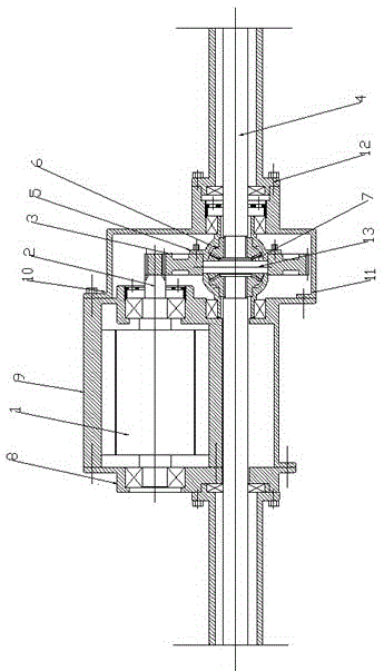
[0014] figure 1 It is a schematic diagram of the structure of the present invention, as shown in the figure: a miniature electric vehicle drives the rear axle, including a motor (1), a motor output gear shaft (2), a primary driven gear (3), and left and right driving half shafts (4) , the primary driven gear (3) is arranged under the motor output gear shaft (2), the primary driven gear (3) is connected to the differential case (5) through bolts, and the left and right driving half shafts ( 4) Located on both sides of the primary driven gear (3), fixed by the differential case (5), the left and right drive axle shafts (4) are connected to the planetary gear (7) through the axle gear (6), The side gear (6) is fixed inside the differential case (5).

[0015] The motor (1) is connected with an engine front end cover (8) and an engine rear end cover (9), and the engine rear end cover (9) is connected with a first-stage reduction box (10) through bolts, and the reduction box (10 )...


PUM


Abstract

The invention discloses a driving rear axle of a mini electric vehicle. The driving rear axle of the mini electric vehicle adopts a transmission structure with a motor, a single-reduction gearbox and a differential, is simple and compact in structure and high in transmission efficiency as compared with the prior art, and is more suitable for mini electric vehicles. Simultaneously, a motor output gear shaft which is processed by a cold extrusion molding technique has the characteristics of low number of teeth and high strength, and is suitable for the transmission structure with the motor, single-reduction gearbox and differential. The motor and reduction gearbox integrated case is convenient for mounting and disassembly, reduces the required space for arrangement, and solves the problem that the inner space of the mini electric vehicle is insufficient.

Description

technical field [0001] The invention relates to a thermal fatigue testing machine applied to the metal bellows of the automobile exhaust system, more specifically, it relates to a kind of independent and combined Motion thermal fatigue testing machine. Background technique [0002] Electric vehicles use vehicle-mounted power batteries as power to drive vehicles. Because electric vehicles have the characteristics of energy saving, environmental protection, lightness, and low operating costs, more and more attention has been paid to them. [0003] The existing electric vehicle drive rear axle mostly adopts the transmission structure of motor, secondary reducer and differential, the transmission chain is long, and the structure layout is not compact enough, which makes the transmission efficiency of the whole vehicle low, which is not suitable for micro electric vehicles. When the first-stage reducer is used, the first-stage driving gear shaft needs to have the characteristics...

Claims


Application Information

Patent Timeline
Patent Type & Authority Applications(China)
IPC IPC(8): B60K17/16
CPCB60K17/16
Inventor 崔高健钟博浩李绍松涂永发窦景雷李斌
Owner CHANGCHUN UNIV OF TECH
Learn More