
A circuit breaker and its opening and closing device

A technology of opening and closing, circuit breaker, applied in the direction of protection switch operation/release mechanism, contact drive mechanism, etc., can solve the problems of unreasonable transmission structure, high energy consumption of motor, poor reliability, etc., and achieve stable and reliable transmission efficiency, Reasonable structure design, effect of reducing volume

Active Publication Date: 2019-03-19
浙江合兴电工有限公司
View PDF8 Cites 0 Cited by
  • Summary
  • Abstract
  • Description
  • Claims
  • Application Information

AI Technical Summary

Problems solved by technology

[0005] Therefore, the technical problem to be solved by the present invention is to overcome the problem of large motor energy consumption and poor reliability caused by the unreasonable transmission structure of the circuit breaker opening and closing device in the prior art, so as to provide a reasonable transmission structure, low motor energy consumption, and reliable High performance circuit breaker and its opening and closing device

Method used


Image

  • A circuit breaker and its opening and closing device
  • A circuit breaker and its opening and closing device
  • A circuit breaker and its opening and closing device

Examples


Embodiment 1

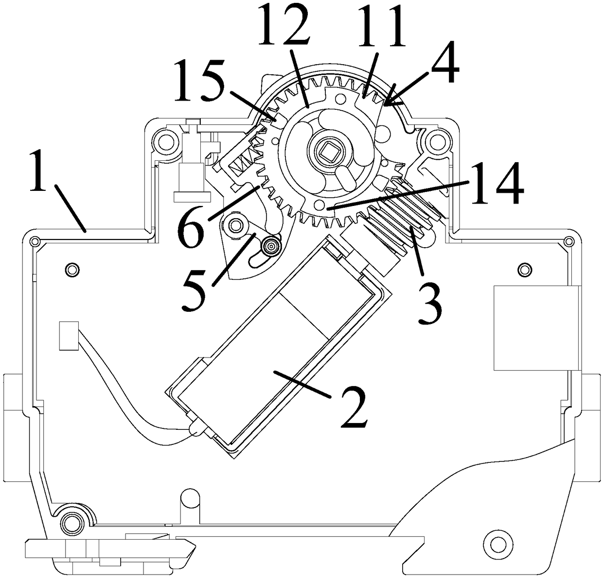
[0044] Independent claim 1 describes an opening and closing device, such as figure 1 As shown, it includes a housing 1, a motor 2 disposed in the housing 1, a worm 3 driven by the motor 2, and a worm gear assembly 4 matched with the worm,

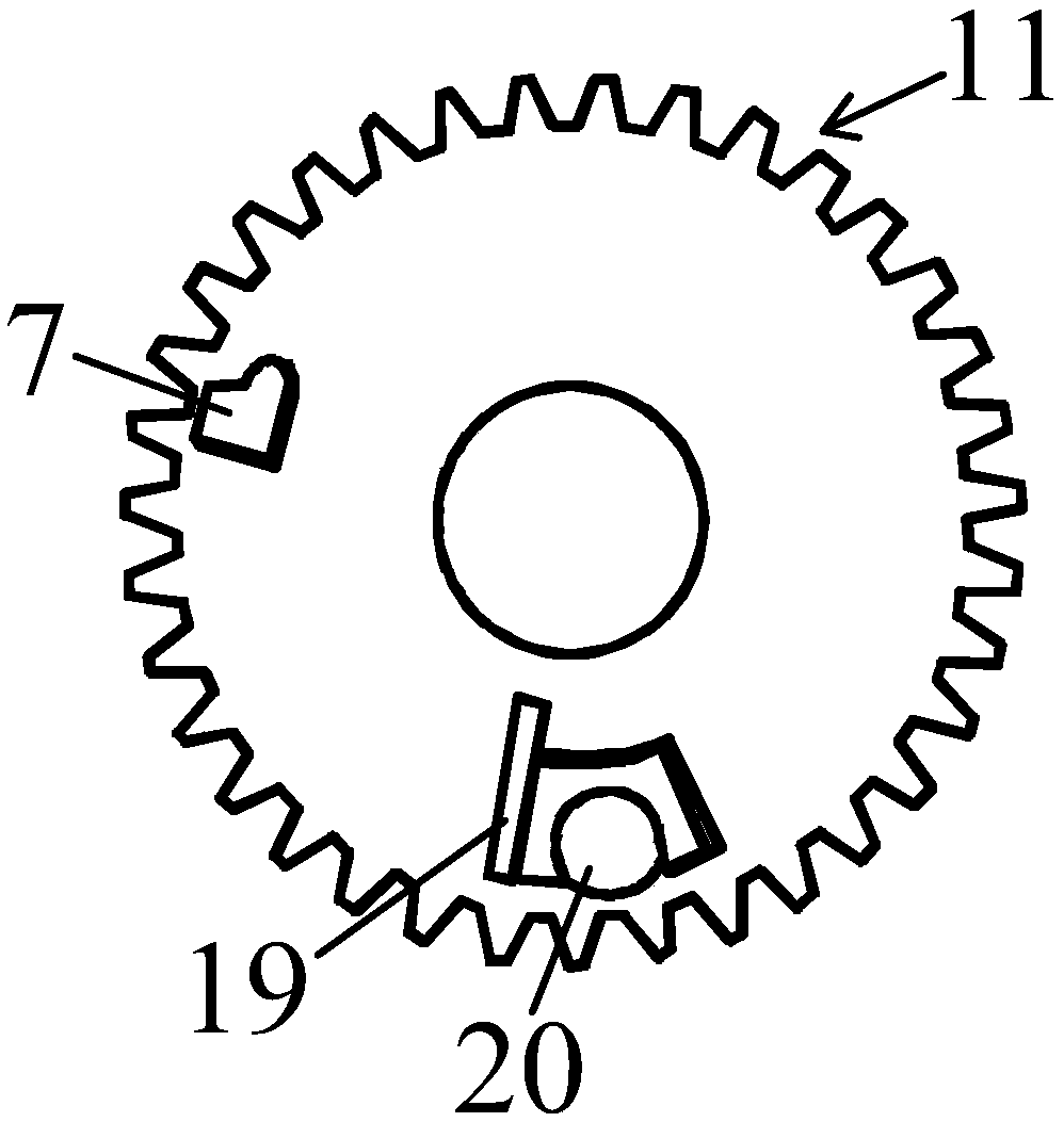
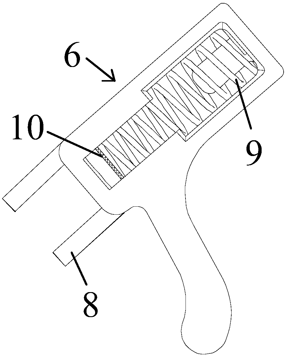
[0045] Such as figure 1 and figure 2 As shown, it also includes a linkage rod 5 arranged on one side of the worm gear assembly 4 and pivotally connected to the inner wall of the housing 1 for driving the circuit breaker to open, and linearly movable on the worm gear assembly 4 The push rod 6 on the inner wall of the housing between the linkage rod 5; the worm gear assembly 4 is provided with a first worm gear boss 7 corresponding to the push rod 6, and the first worm gear The boss 7 rotates in the opposite direction with the worm gear assembly 4, slides along the body of the push rod 6 and pushes the push rod 6 to move in a straight line towards the linkage rod 5, and then pushes the linkage rod 5 to rotate to realize circuit breaker sw...

Embodiment 2

[0067] An opening and closing device, such as figure 1 As shown, it includes a housing 1, a motor 2 disposed in the housing 1, a worm 3 driven by the motor 2, and a worm gear assembly 4 matched with the worm,

[0068] Such as figure 1 and figure 2 As shown, it also includes a linkage rod 5 arranged on one side of the worm gear assembly 4 and pivotally connected to the inner wall of the housing 1 for driving the circuit breaker to open, and linearly movable on the worm gear assembly 4 The push rod 6 on the inner wall of the housing between the linkage rod 5; the worm gear assembly 4 is provided with a first worm gear boss 7 corresponding to the push rod 6, and the first worm gear The boss 7 rotates in the opposite direction with the worm gear assembly 4, slides along the body of the push rod 6 and pushes the push rod 6 to move in a straight line towards the linkage rod 5, and then pushes the linkage rod 5 to rotate to realize circuit breaker switch off.

[0069] The above-...


PUM


Abstract

A switching-on / off device comprises a shell, a motor arranged inside the shell, a worm driven by the motor, and a worm gear component matching the worm. The switching-on / off device further comprises a linkage rod which is arranged at one side of the worm gear component and pivoted to the inner wall of the shell and is used for driving the circuit breaker to be switched off, and a push rod which is arranged on the inner wall of the shell between the worm gear component and the linkage rod in a linear movement way. The worm gear component is provided with a first worm gear boss corresponding to the push rod. For switching-off operation, the first worm gear boss rotates reversely with the worm gear component, slides along the rod body of the push rod and pushes the push rod to move linearly to the linkage rod, so as to push the linkage rod to rotate and switch off the circuit breaker.

Description

technical field [0001] The invention relates to the technical field of low-voltage electrical appliances, in particular to a circuit breaker and an opening and closing device thereof. Background technique [0002] my country's power supply network is constantly developing toward the implementation of intelligence, and the intelligence of the power supply network cannot lack the terminal actuator of the power supply network - the miniature circuit breaker. The miniature circuit breaker executes the upper-end signal to complete the tripping and closing actions. Therefore, the current development trend of miniature circuit breakers is that in addition to the traditional manual opening and closing and overcurrent and overload automatic tripping functions, it also needs to have an electric opening and closing function (commonly known as automatic opening and closing function) to achieve remote control; especially It is a combination of smart meters to realize the function of aut...

Claims


Application Information

Patent Timeline
Patent Type & Authority Patents(China)
IPC IPC(8): H01H71/10H01H3/32
CPCH01H3/32H01H71/10
Inventor 旷荣昌王军军旷东平邹爱军张利伟
Owner 浙江合兴电工有限公司
Learn More