
Optical label identification method

An identification method and optical tag technology, which is applied in the field of optical communication, can solve the problems of two-dimensional code recognition distance, poor directivity, and inability to meet the requirements for directional information acquisition, and achieve the effect of improving the recognition distance

Active Publication Date: 2017-02-01
BEIJING WHYHOW INFORMATION TECH CO LTD
View PDF6 Cites 30 Cited by
  • Summary
  • Abstract
  • Description
  • Claims
  • Application Information

AI Technical Summary

Problems solved by technology

[0002] At present, in the information interaction based on mobile terminals, in order to identify and connect various information platform targets, two-dimensional code technology or wireless identification is usually used to establish information links between demanders and suppliers, but the two-dimensional code The method has a short recognition distance, which is specifically manifested in a low ratio of recognition distance to codeword graphic size; although the radio signal recognition distance is long, its directivity is poor, and there may be multiple usable targets in the target area, which cannot be oriented; The long-distance directional information acquisition requirements cannot meet the use requirements in terms of consumer shopping, information acquisition, and information delivery.

Method used


Image

  • Optical label identification method
  • Optical label identification method
  • Optical label identification method

Examples


Embodiment Construction

[0029] The present invention will be further described in detail below in conjunction with specific embodiments, which are explanations of the present invention rather than limitations.

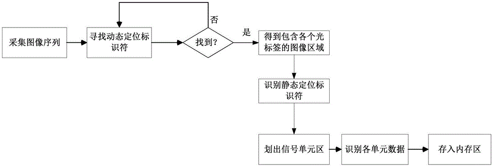
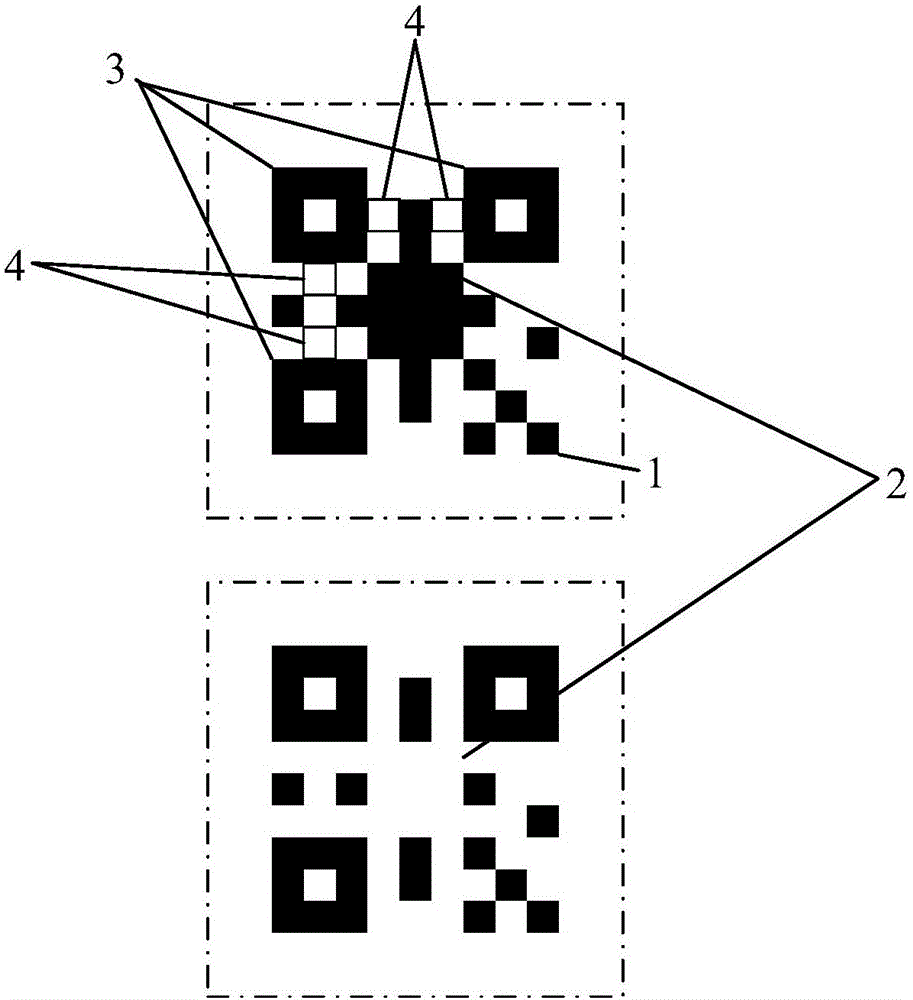
[0030] The optical label identification method of the present invention includes an optical label for information encoding and a mobile terminal for information decoding; the optical label includes a signal unit and a positioning mark; the signal unit includes several static image units, and the positioning mark includes several A dynamic flashing light-emitting unit, and a plurality of static graphic signs, the light-emitting area of ​​the light-emitting unit in the positioning mark is larger than the area of ​​the image unit in the signal unit; the information content transmitted through the image attribute coding of the image unit; the mobile terminal includes An image acquisition device and an image processing module, the image acquisition device is used to collect the coded image of the o...


PUM


Abstract

The present invention provides an optical label identification method. The system comprises an optical label configured for information encoding and a mobile terminal configured for information decoding; the optical label includes a signal unit and location identification; the signal unit includes a plurality of static image units, and the location identification includes a plurality of dynamically sparkling luminescence units and a plurality of static graphical signs; the information content is encoded and transmitted through image attributes of the static image units; the mobile terminal includes an image collection device and an image processing module; the image collection device is configured to collect the coding images of the optical label; the image processing module is configured to decode the coding images; and the optical label performs information transmission through the static images to satisfy the directionality requirement, the primary localization of the optical label is performed through the dynamically sparkling location identifier, and the accurate location of the optical label is performed through the location identifier of the static image, so that the requirement of identifying multiple optical labels at the same time is satisfied, and the identification distance is greatly improved.

Description

technical field [0001] The invention relates to optical communication technology, in particular to an identification method of an optical label. Background technique [0002] At present, in the information interaction based on mobile terminals, in order to identify and connect various information platform targets, two-dimensional code technology or wireless identification is usually used to establish information links between demanders and suppliers, but the two-dimensional code The method has a short recognition distance, which is specifically manifested in a low ratio of recognition distance to codeword graphic size; although the radio signal recognition distance is long, its directivity is poor, and there may be multiple usable targets in the target area, which cannot be oriented; The long-distance directional information acquisition requirements cannot meet the usage requirements in terms of consumption shopping, information acquisition, and information transmission. C...

Claims


Application Information

Patent Timeline
IPC IPC(8): G06K7/10G06K17/00G06K19/06
CPCG06K7/10G06K17/0016G06K19/06009G06K19/06046G06K2007/10485G06K17/00G06K19/06
Inventor 方俊王晓东李江亮苏爱民
Owner BEIJING WHYHOW INFORMATION TECH CO LTD
Learn More