
Wearable system

An information acquisition module, information selection technology, applied in the direction of instrument, electrical digital data processing, input/output of user/computer interaction, etc., can solve the problem of wearable device complex structure, inability to flexibly match functional modules, and inaccurate measurement results and other problems, to avoid interference, extend continuous use time, and reduce costs

Inactive Publication Date: 2017-02-01
SHANGHAI JIAO TONG UNIV
View PDF5 Cites 1 Cited by
  • Summary
  • Abstract
  • Description
  • Claims
  • Application Information

AI Technical Summary

Problems solved by technology

[0003] However, the functions provided by these wearable devices in the existing technology are relatively single, and the measurement results of various parameters of the human body are not accurate
In addition, in the prior art, each functional module of the wearable system is fixedly set on the wearable device, and its specific position and connection relationship are determined. Therefore, when the user only needs one or a few functions, it is impossible to flexibly match various modules according to needs. functional module
More importantly, in the existing technology, the sensors in various wearable devices are based on different principles to complete the detection of human body signs signals. Therefore, when these different sensors are integrated into a system, it is Different signal conversion circuits are required to process and display different detection signals, thus complicating the structure of wearable devices

Method used


Image

  • Wearable system
  • Wearable system

Examples


Embodiment Construction

[0019] The technical solution of the present invention will be described in detail below in conjunction with the accompanying drawings and embodiments.

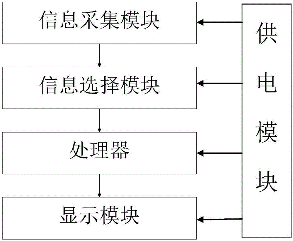
[0020] Such as figure 1 As shown, the wearable system of the present invention includes an information collection module, an information selection module, a processor, a display module and a power supply module;

[0021] The information acquisition module includes a plurality of sensors and a signal conversion unit connected to the sensors. The sensors are used to detect external environmental parameters and human body sign parameters. The signal conversion unit is based on thin film transistors and can convert various The electrical signal is converted into a voltage signal.

[0022] The information selection module is connected with the information collection module, and is used for automatically switching the signals output by the information collection module.

[0023] The processor is respectively connected with the in...


PUM


Abstract

The invention discloses a wearable system. The wearable system comprises an information acquisition module, an information selection module, a processor, a display module and a power supply module, wherein the information acquisition module comprises a plurality of sensors and a signal conversion unit connected with the sensors; the sensors are used for detecting external environment parameters and human physical sign parameters; the signal conversion unit can be used for converting various electrical signals detected by the sensors into a voltage signal; the information selection module is connected with the information acquisition module and is used for automatically switching a signal outputted by the information acquisition module; the processor is connected with the information selection module and the display nodule, and is used for receiving a signal transmitted by the information selection module, calculating according to a preset model, and transmitting a calculation result to the display module; the display module is used for receiving the calculation result transmitted by the processor, and reminding a wearer according to the calculation result; the power supply module is connected with the information acquisition module, the information selection module, the processor and the display module and provides a power supply for the modules. According to the wearable system disclosed by the invention, an output signal is unified, the structure is simplified, power consumption is reduced and the cost is reduced.

Description

technical field [0001] The invention relates to the technical field of wearable devices, in particular to a wearable system for real-time monitoring of human body signs and environmental signals. Background technique [0002] In recent years, with the increasing development of technology, smart wearable devices have gradually become a new technology trend. Among them, smart wearable equipment, as a product closely related to people's daily life, is gaining more and more attention. For example, smart watches, smart bracelets, smart insoles, etc. have widely entered people's lives. [0003] However, the functions provided by these wearable devices in the existing technologies are relatively single, and the measurement results of various parameters of the human body are not accurate. In addition, in the prior art, each functional module of the wearable system is fixed on the wearable device, and its specific location and connection relationship are determined. Therefore, when...

Claims


Application Information

Patent Timeline
Patent Type & Authority Applications(China)
IPC IPC(8): G06F3/01
CPCG06F3/011
Inventor 郭小军陈苏杰唐伟卓本刚
Owner SHANGHAI JIAO TONG UNIV
Learn More