
Electronic illuminating device under humid environment

A wet environment, lighting device technology, applied in the direction of lighting devices, fixed lighting devices, lighting device components, etc., can solve the problems of high price, short-circuit burning of drive circuit components, and protection when the circuit cannot be opened, so as to achieve precise control and improve The effect of high service life and high integration

Inactive Publication Date: 2017-02-01
桂林大创科技有限公司
View PDF4 Cites 3 Cited by
  • Summary
  • Abstract
  • Description
  • Claims
  • Application Information

AI Technical Summary

Problems solved by technology

[0002] The service life of LED lighting is much higher than that of ordinary incandescent lamps, but due to the high price, when it is damaged, the economic loss to the user is also large, so it is necessary to better protect the LED equipment and install it in the bathroom. Most of the causes of damage to the LED lamps are that the water droplets condensed on the ceiling of the bathroom fell into the lamps and caused a short circuit and burned the drive circuit components. At the same time, the high temperature environment in the bathroom is not conducive to the heat dissipation in the lamps. There are also certain defects, and it is impossible to provide relative protection for open circuits.

Method used


Image

  • Electronic illuminating device under humid environment
  • Electronic illuminating device under humid environment
  • Electronic illuminating device under humid environment

Examples


Embodiment Construction

[0016] The following will clearly and completely describe the technical solutions in the embodiments of the present invention with reference to the accompanying drawings in the embodiments of the present invention. Obviously, the described embodiments are only some, not all, embodiments of the present invention. Based on the embodiments of the present invention, all other embodiments obtained by persons of ordinary skill in the art without making creative efforts belong to the protection scope of the present invention.

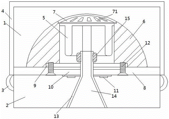
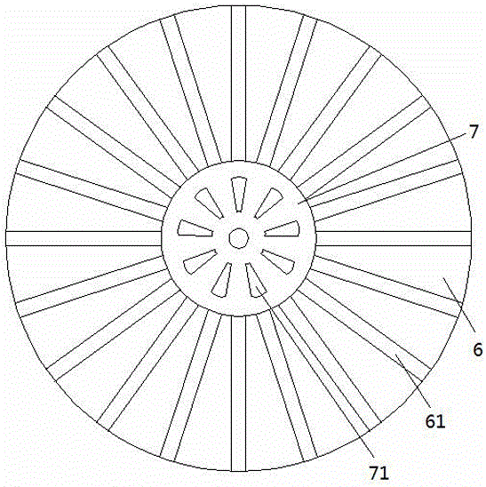
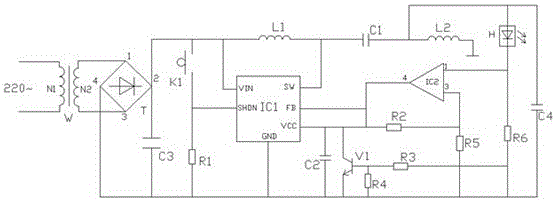
[0017] see Figure 1~3 , in an embodiment of the present invention, an electronic lighting device in a humid environment, including a driving chamber 1, a lamp chamber 2, a driving circuit assembly 5, a radiator 6, a top cover 7 and an insulating member 13, and the driving chamber 1 is arranged in Above the lamp chamber 2, the insulator 13 runs through the drive cavity 1 and the lamp chamber 2, and the inside of the insulator 13 forms a ventilation cavity 14, ...


PUM


Abstract

The invention discloses an electronic illuminating device under a humid environment. The electronic illuminating device comprises a drive cavity, a lamp room, a drive circuit assembly, a radiator, a top cover and an insulating part, wherein the drive cavity is arranged above the lamp room; the insulating part penetrates through the drive cavity and the lamp room; a ventilating cavity is formed inside the insulating part; the upper end of the insulating part is connected with the drive circuit assembly arranged in the drive cavity; the radiator is arranged in the drive cavity; an accommodating cavity is arranged in the center of the radiator; and a heat transfer plate is embedded into the bottom of the radiator. According to the electronic illuminating device disclosed by the invention, the ventilating cavity is arranged in the insulating part, the accommodating cavity is arranged in the radiator, an air vent is formed in the top cover, and the air vent, the accommodating cavity and the ventilating cavity are sequentially connected to form a radiating air channel which generates convection with outside air to dissipate heat in the drive cavity as quickly as possible, and a waterproof plate covers the outer part of the drive cavity, so that the problem that short-circuit damage, due to the fact that water drops gathered on a bathroom ceiling drop in the drive cavity, of the drive circuit assembly is avoided, and therefore, the service life of the device is prolonged.

Description

technical field [0001] The invention relates to the lighting field, in particular to an electronic lighting device in a humid environment. Background technique [0002] The service life of LED lighting is much higher than that of ordinary incandescent lamps, but due to the high price, when it is damaged, the economic loss to the user is also large, so it is necessary to better protect the LED equipment and install it in the bathroom. Most of the causes of damage to the LED lamps are that the water droplets condensed on the ceiling of the bathroom fell into the lamps and caused a short circuit and burned the drive circuit components. At the same time, the high temperature environment in the bathroom is not conducive to the heat dissipation in the lamps. There are also certain defects, and it is impossible to perform relative protection against the open circuit situation. Contents of the invention [0003] The purpose of the present invention is to provide an electronic lig...

Claims


Application Information

Patent Timeline
Patent Type & Authority Applications(China)
IPC IPC(8): F21S8/00F21V25/00F21V17/12F21V23/00F21V29/70F21V29/77F21V29/83F21V31/00F21V19/00H05B33/08F21V29/89F21Y115/10H05B44/00
CPCF21S8/033F21V17/12F21V19/001F21V23/003F21V25/00F21V29/70F21V29/77F21V29/83F21V29/89F21V31/00H05B45/37
Inventor 巢雨董珉董姗姗
Owner 桂林大创科技有限公司
Learn More