
Real-time monitoring method for highest temperature in cylinder head of internal combustion engine

A technology of internal combustion engine cylinder and maximum temperature, which is applied in mechanical equipment, engine components, machines/engines, etc. It can solve problems such as many small holes for measurement, accelerated cylinder head damage, and inability to directly measure the maximum temperature of the fire surface, etc., to ensure reliability performance, high application efficiency

Active Publication Date: 2017-02-01
HUAZHONG UNIV OF SCI & TECH
View PDF6 Cites 9 Cited by
  • Summary
  • Abstract
  • Description
  • Claims
  • Application Information

AI Technical Summary

Problems solved by technology

However, the above method cannot directly measure the maximum temperature of the "nose bridge area" of the fire surface, and there are many small holes for measurement, which will affect the temperature field distribution of the cylinder head, reduce the strength of the cylinder head, and accelerate the damage of the cylinder head; in addition , the fluid-solid coupling numerical method needs to carry out numerical simulation offline on the temperature data measured in the experiment in step 1, and it is impossible to know the maximum temperature in the cylinder head in real time when the internal combustion engine is working, so it is impossible to calculate the maximum temperature of the cylinder head under the actual working state of the internal combustion engine. real time monitoring

Method used


Image

  • Real-time monitoring method for highest temperature in cylinder head of internal combustion engine
  • Real-time monitoring method for highest temperature in cylinder head of internal combustion engine
  • Real-time monitoring method for highest temperature in cylinder head of internal combustion engine

Examples


Embodiment Construction

[0029] In order to make the object, technical solution and advantages of the present invention clearer, the present invention will be further described in detail below in conjunction with the accompanying drawings and embodiments. It should be understood that the specific embodiments described here are only used to explain the present invention, not to limit the present invention.

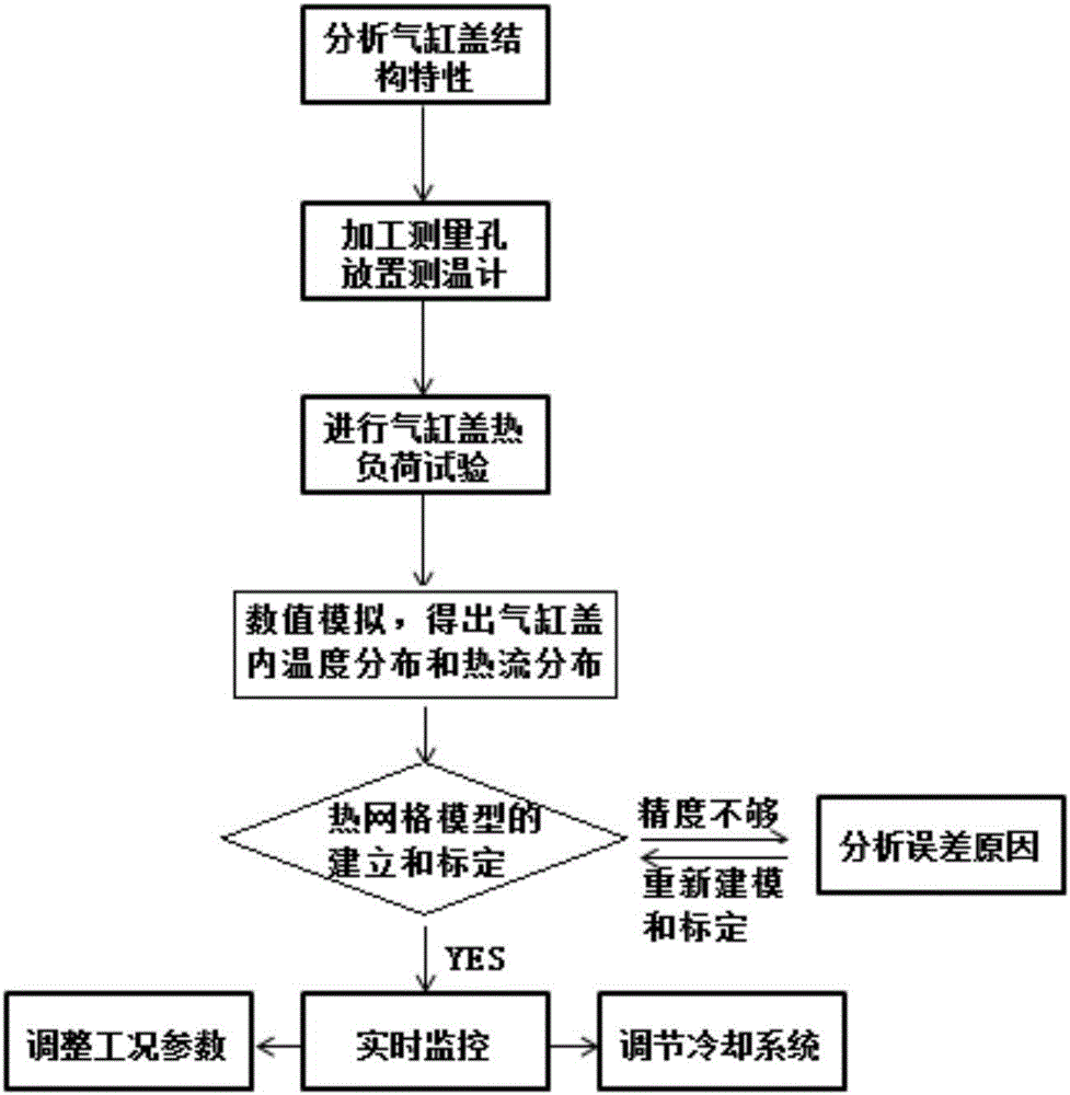
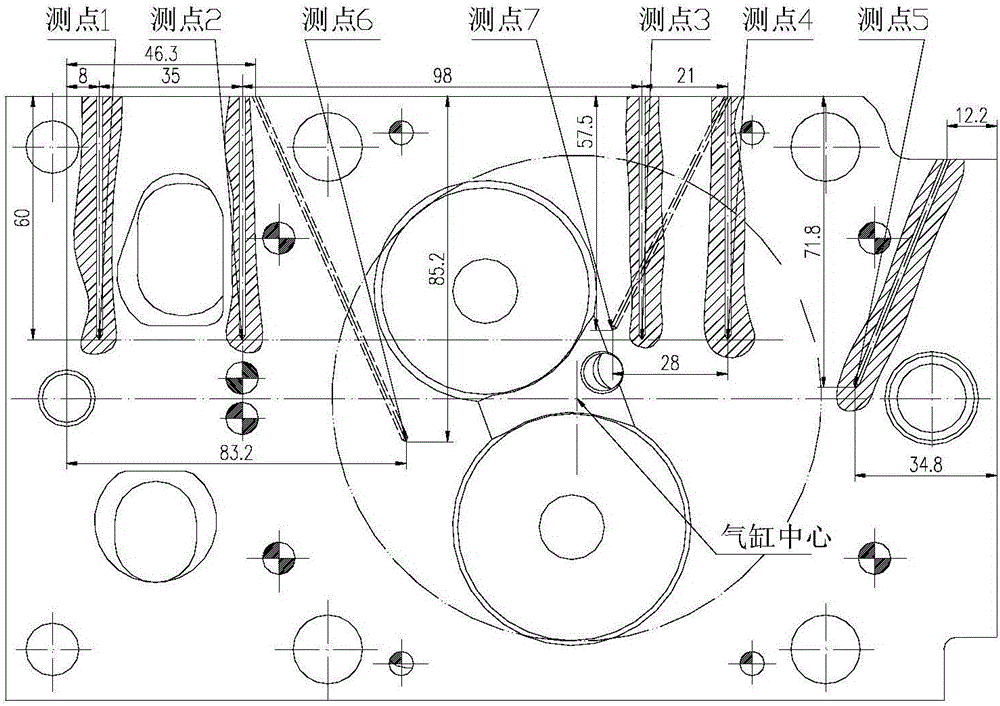
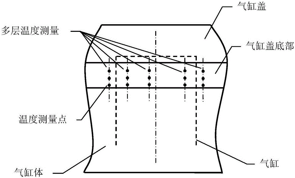
[0030] The real-time monitoring method of the highest temperature in the internal combustion engine cylinder head of the embodiment of the present invention, its implementation process is as follows figure 1 shown. In this embodiment, a heavy-duty diesel engine is taken as an example to illustrate the method for monitoring the maximum temperature in the cylinder head, but the method of the present invention is not limited to the above-mentioned diesel engine, and can also be other types of diesel engines, gasoline engines or gas internal combustion engines.

[0031] The method specifically include...


PUM


Abstract

The invention discloses a real-time monitoring method for the highest temperature in a cylinder head of an internal combustion engine. The real-time monitoring method includes the steps that (1) a temperature measuring experiment for the cylinder head of the internal combustion engine is conducted, and numerical simulation of a cylinder head temperature field is conducted, so that the highest temperature, temperature distribution and heat flow distribution in the cylinder head are obtained; (2) numerical simulation of external flow of the internal combustion engine is carried out, and the position of a peripheral temperature measuring point on the cylinder head is obtained; (3) a correlation model for the highest temperature in the cylinder head and the temperature at the peripheral temperature measuring point is determined by means of results of the highest temperature, temperature distribution and heat flow distribution; and (4) during actual work of the internal combustion engine, by measuring the temperature of the peripheral temperature measuring point of the cylinder head in real time with the peripheral temperature measuring point as a temperature measuring point and utilizing a calibrated thermal network model, the highest temperature in the cylinder head can be obtained in real time through inverse estimation. By means of the real-time monitoring method, real-time monitoring on the highest temperature of high-temperature parts which cannot be directly measured or are not suitable for being directly measured for a long time can be achieved, and the reliability of the parts is ensured.

Description

technical field [0001] The invention belongs to the technical field of internal combustion engines, and in particular relates to a method for real-time monitoring of the maximum temperature in a cylinder head of an internal combustion engine. Background technique [0002] As one of the most widely used power machines, the internal combustion engine is widely used in automobiles, ships, railways, construction, agriculture and other fields, and has become an indispensable part of national construction. With the development of my country's economy and the advancement of science and technology, the internal combustion engine industry has developed vigorously, and the assembly of internal combustion engines in mobile machinery such as automobiles, ships, and aircraft has increased significantly. With the development of internal combustion engine technology and the improvement of social needs, the power density of internal combustion engines is getting higher and higher, which mak...

Claims


Application Information

Patent Timeline
IPC IPC(8): F02B77/08
CPCF02B77/089
Inventor 王兆文王桦彬
Owner HUAZHONG UNIV OF SCI & TECH
Learn More