


Quick Research
Generate reliable direction feasibility study reports for your R&D in just a few steps.

Technical Q&A
Discover and master advanced knowledge NOW. Basics, ideas, possibilities, all at once.

Find Solutions
As an expert in R&D theories, this can generate solutions to your technical problems instantly.

Evaluate Feasibility
Analyze your overall solution with one click, know your potential R&D risks in advance.

Monitor Landscape
Get weekly tech updates, stay abreast of the latest tech innovations and key insights.
Disc spring shock absorber with adjustable initial rigidity
A disc spring and initial stiffness technology, applied in the field of damping devices, can solve problems such as waste, increase in length of the damper, deformation of two sets of disc springs, etc., and achieve the effects of reducing the cost of vibration isolation, preventing torsion, and preventing resonance
- Summary
- Abstract
- Description
- Claims
- Application Information
AI Technical Summary
Problems solved by technology
Method used
Image

Examples
example 1
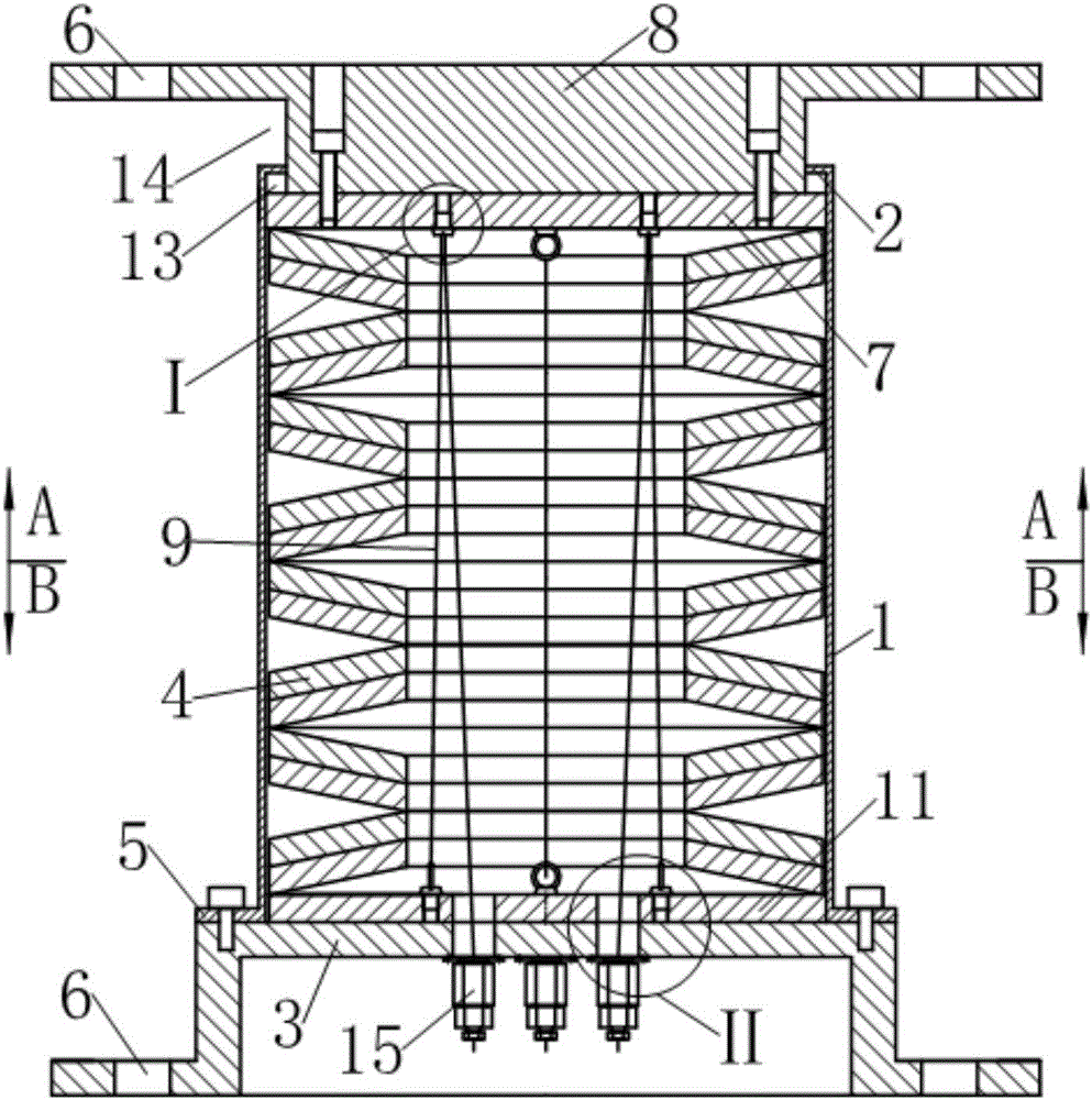
[0039] See Figure 1~6 The damper described in this example is a vertical seismic isolation device (also called vertical seismic isolation support) used for building seismic resistance, which includes a guide sleeve 1, a first end cover 2, a second end cover 3 , Disc spring group 4 and back pressure device.
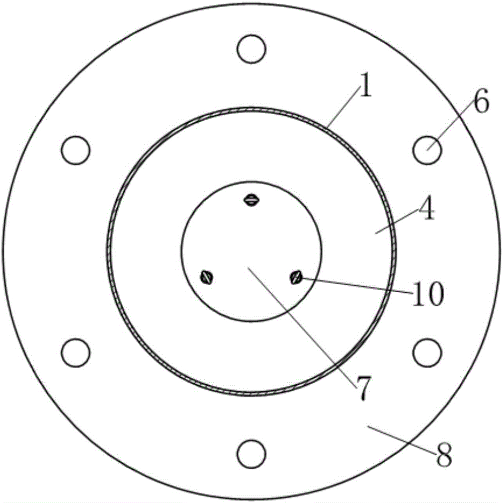
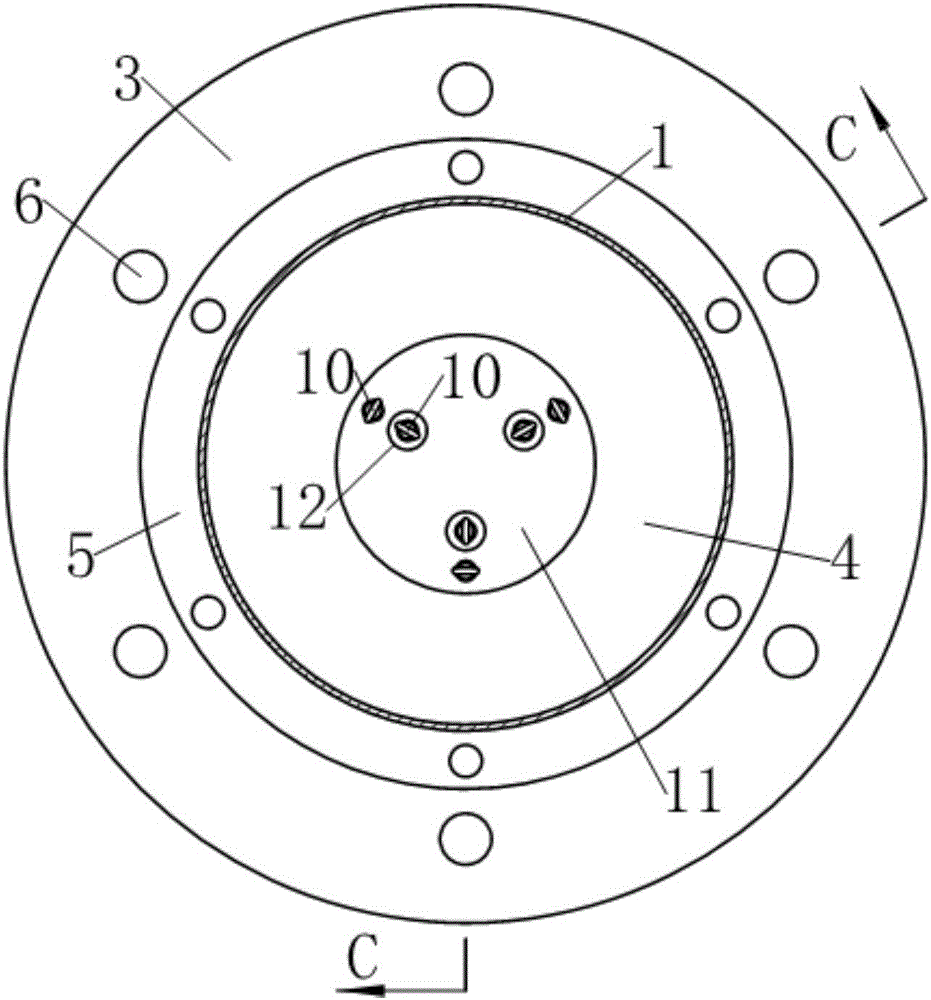
[0040] See Figure 1~3 The guide sleeve 1 has a circular tube shape, the upper end of which radially shrinks inwardly to form a first end cover 2 with a guide hole in the center, and the lower end radially extends outward to form a flange 5. The middle part of the second end cover 3 bulges upward to form an inverted washbasin shape, and the peripheral edges are provided with mounting holes 6, and the guide sleeve 1 is fixed to the middle part of the bulge by a flange 5 provided at the lower end. Upper surface.
[0041] See Figure 1~3 , The driving member is composed of a dynamic pressure plate 7 and an upper connecting plate 8. The upper connecting plate 8 is disc-shaped, wit...
example 2
[0059] See Figure 12-16 The damper described in this example is also a vertical seismic isolation device used for building earthquake resistance, and on the basis of example 1, the following improvements have been made: (1) The pre-compression wire rope 9 is increased by three Up to six; (2) Replace the eyebolt 10 as the direction changing element of the wire rope with a U-shaped member 16; (3) Increase the wire rope self-locking tension anchor 15 at the other end of the pre-compressed wire rope 9 to six; (4) ) Change the back pressure device to:
[0060] The said back pressure device consists of six pre-compressed steel wire ropes 9, six U-shaped members 16 as wire rope direction changing elements, a floating back-pressure steel plate 11, six eye screws 10 for fixing one end of the pre-compressed steel wire rope 9 and six fixed pre-compression steel wires. The wire rope self-locking tension anchor 15 at the other end of the pressure wire rope 9 is composed of;
[0061] The float...
example 3
[0067] See Figure 17-19 This example is a damper used for seismic reinforcement of building structures. The damper includes a guide sleeve 1. A first end cover 2 and a second end cover 3 are fixed at both ends of the guide sleeve 1, and a dish-shaped The spring set 4, a drive member extends into the guide sleeve 1 from the center of the first end cover 2 at the end of the guide sleeve, and is pressed on the disc spring set 4; wherein the drive member is composed of a dynamic pressure plate 7 and An integrated first driving rod 17 is formed, and the end of the first driving rod 17 is provided with a hinge hole 18.
[0068] See Figure 17 A second driving rod 19 integrally connected to the second end cover 3 is provided on the outside, and a hinge hole 18 is also provided at the end of the second driving rod 19.
[0069] See Figure 17-21 , Said guide sleeve 1 is provided with a back pressure device, the back pressure device consists of three pre-compressed steel wire ropes 9, thre...
PUM
 Abstract
Description
Claims
Application Information
 - R&D Engineer
- R&D Manager
- IP Professional
- Industry Leading Data Capabilities
- Powerful AI technology
- Patent DNA Extraction
Browse by: Latest US Patents, China's latest patents, Technical Efficacy Thesaurus, Application Domain, Technology Topic, Popular Technical Reports.
© 2024 PatSnap. All rights reserved.Legal|Privacy policy|Modern Slavery Act Transparency Statement|Sitemap|About US| Contact US: help@patsnap.com