A purely mechanical impact compactor

A tamping machine, mechanical technology, applied in soil protection, construction, infrastructure engineering and other directions, can solve the problems of small space, high maintenance costs, unfavorable promotion, etc., to avoid hydraulic systems, low maintenance costs, and conducive to promotion. Effect

Active Publication Date: 2018-08-24
宣城市政建设集团有限公司
View PDF7 Cites 0 Cited by
  • Summary
  • Abstract
  • Description
  • Claims
  • Application Information

AI Technical Summary

Problems solved by technology

[0002] When backfilling structures such as the back of bridges and culverts in highway engineering, due to the narrow space, ordinary road rollers cannot work normally, and ordinary hand-held small compaction machines have too small shock force, poor compaction effect, and quality cannot be guaranteed
At present, the price of some special fast hydraulic compactors produced by machinery manufacturers is relatively high, and the price of hydraulic compactors carried by loaders is even higher. In addition, the workload of compaction such as the back of the table is generally not very large, and the utilization rate of the equipment is low, which is not economically cost-effective.
[0003] In order to solve the above problems, the Chinese patent (authorized announcement number: CN20525803U) discloses a simple hydraulic impact compactor, including a vehicle frame, a rotary platform and a rammer, although the device can reduce the manufacturing cost of the hydraulic compactor to a certain extent. cost, but the device still contains a hydraulic system, so the bad problems caused by the hydraulic system have not been solved, and the device uses the hydraulic system to maintain the movement of the rammer, and the maintenance cost is high, which is not conducive to popularization

Method used


Image

  • A purely mechanical impact compactor

Examples


Embodiment Construction

[0015] The following will clearly and completely describe the technical solutions in the embodiments of the present invention with reference to the accompanying drawings in the embodiments of the present invention. Obviously, the described embodiments are only some, not all, embodiments of the present invention. Based on the embodiments of the present invention, all other embodiments obtained by persons of ordinary skill in the art without making creative efforts belong to the protection scope of the present invention.

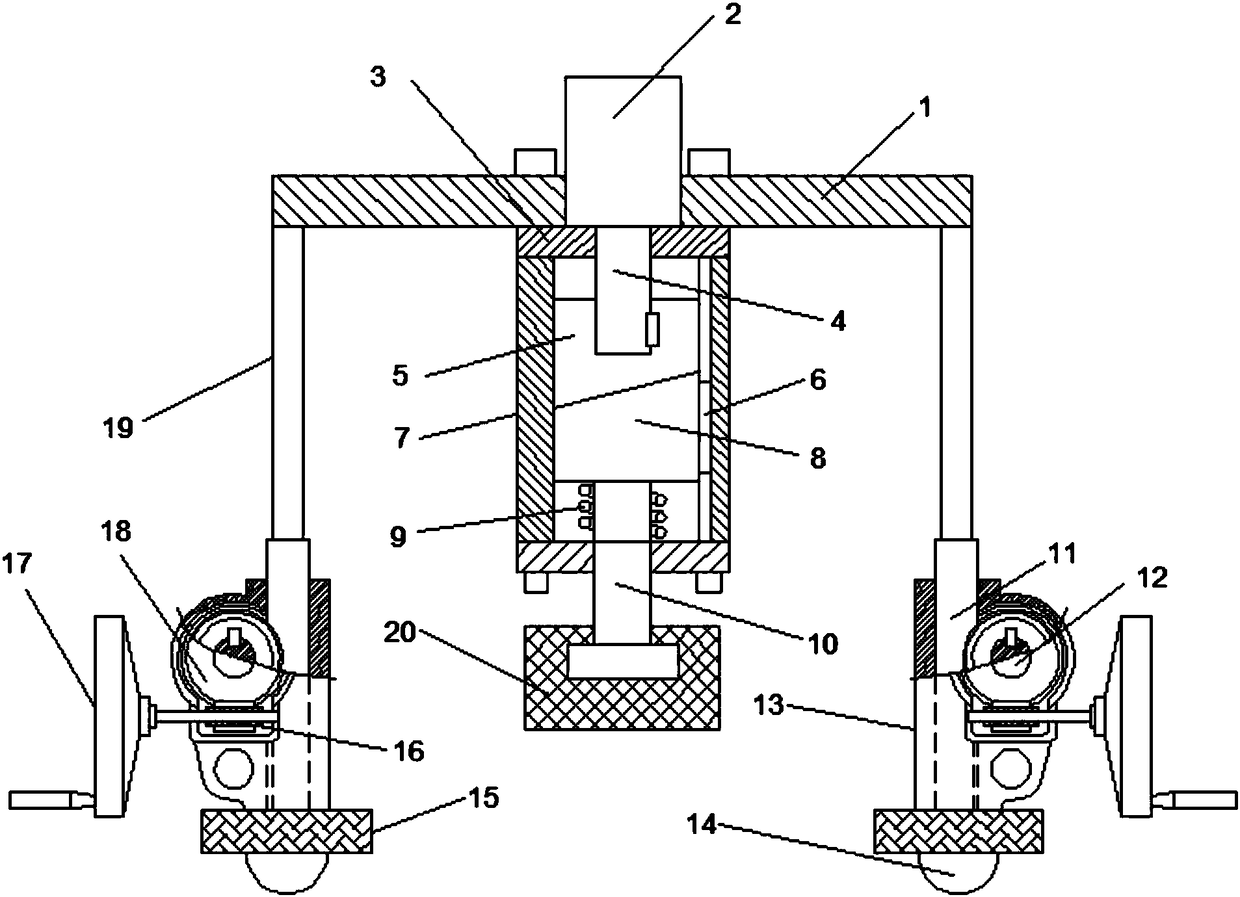
[0016] see figure 1 , in an embodiment of the present invention, a purely mechanical impact compactor includes a support beam 1 and a support sleeve 13, a drive motor 2 is provided in the middle of the support beam 1, and the drive motor 2 is connected to the support beam 1 through a fixing bolt. The lower end of the motor 2 is connected with a driving shaft 4, and the lower end of the driving shaft 4 is connected with an upper cam 5, the left side of the lowe...


PUM


Abstract

The invention discloses a purely mechanical impact rammer compactor which comprises a supporting beam and supporting sleeves. A drive motor is arranged in the middle of the supporting beam. The lower end of the drive motor is connected with a drive shaft. The lower end of the drive shaft is connected with an upper cam. A lower cam is arranged at the lower end of the upper cam. The lower end of the lower cam is connected with a cam shaft. A reset spring is arranged on the outer side of the upper end of the cam shaft. The lower end of the cam shaft is connected with a rammer cone. A guide sleeve is arranged on the outer side of the upper cam and the lower cam. A guide key is connected between the guide sleeve and the lower cam. A gear shaft is arranged in the middle of each supporting sleeve. The upper end of each gear shaft is connected with another supporting beam. A worm gear is arranged on the outer side of each gear shaft in an engaged mode. Each supporting sleeve is connected to the middle of the corresponding worm gear through a rotary shaft. The lower end of each worm gear is connected with a worm. The lower end of each supporting sleeve is connected with a buffer block, and the lower end of each buffer block is connected with a traveling wheel. The ramming work of a rammer is achieved through a purely mechanical mechanism, no hydraulic system is applied, the maintenance cost is low, maintenance is convenient, and popularization is facilitated.

Description

technical field [0001] The invention relates to the field of ramming mechanical equipment, in particular to a purely mechanical impact ramming machine. Background technique [0002] When backfilling structures such as the back of bridges and culverts in highway engineering, due to the narrow space, ordinary road rollers cannot work normally, and ordinary hand-held small compaction machines have too small shock force, poor compaction effect, and quality cannot be guaranteed. At present, the price of some special fast hydraulic compactors produced by machinery manufacturers is relatively high, and the price of hydraulic compactors carried by loaders is even higher. In addition, the workload of compaction such as the back of the table is generally not very large, and the utilization rate of the equipment is low, which is not economically cost-effective. . [0003] In order to solve the above problems, the Chinese patent (authorized announcement number: CN20525803U) discloses a...

Claims


Application Information

Patent Timeline
Patent Type & Authority Patents(China)
IPC IPC(8): E02D3/054
CPCE02D3/054
Inventor 不公告发明人
Owner 宣城市政建设集团有限公司
Why Eureka
Try Eureka