
Positioning adjustment workbench of laser scanning detection and servo system

A laser scanning and servo system technology, applied in workbenches, laser welding equipment, manufacturing tools, etc., can solve the problems of narrow space, insufficiency, misoperation, etc., and achieve the effect of simple operation, high precision, safe and reliable operation

Active Publication Date: 2017-02-01
HUBEI NEW HUAGUANG NEW INFORMATION MATERIALS CO LTD
View PDF4 Cites 3 Cited by
  • Summary
  • Abstract
  • Description
  • Claims
  • Application Information

AI Technical Summary

Problems solved by technology

[0003] This adjustment method has the following disadvantages: (1), it cannot meet the movement requirements of the X-axis direction and the Y-axis direction; (2), the movement in the Z-axis direction and the inclination adjustment accuracy of the working panel are not high, and the adjustment process and accuracy Observe with the operator's eyes; (3) Due to the narrow space, the operation is inconvenient, and sometimes there will be misoperation, and the manual adjustment takes a long time; (4) The installation and positioning repeatability of this process equipment is poor; (5) This process equipment The installation is easily limited by the space location. Once the work site changes, the installation of the equipment may be restricted, thus affecting its use
[0004] The above drawbacks have brought a lot of inconvenience to the use of the process equipment

Method used


Image

  • Positioning adjustment workbench of laser scanning detection and servo system

Examples


Embodiment Construction

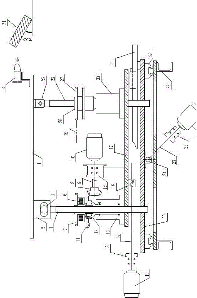
[0024] Such as figure 1 shown. The laser scanning detection and servo system positioning adjustment workbench of the present invention is composed of a laser scanning detection system, an X-axis moving unit, a Y-axis moving unit, a Z-axis moving unit and an angle adjustment system with a horizontal plane.

[0025] Among them, the laser scanning detection system is mainly composed of laser scanning, detection and recorder 5, which is the prior art. The function of the laser scanning detection system is to scan and capture the position of the target 34, detect the location, record and send execution instructions to the servo system.

[0026] The X-axis moving unit mainly includes a laterally moving nut 24, a laterally moving screw mandrel 23, a laterally moving servo motor 21, a laterally moving bearing seat 22, a laterally moving platform 20, and two pairs of linear sliding guide rail pairs 32 installed laterally. The linear sliding guide rail pair 32 is fixedly connected on ...


PUM


Abstract

The invention discloses a positioning adjustment workbench of a laser scanning detection and servo system, and belongs to the technical field of mechanical and electrical control, and the positioning adjustment workbench is mainly used for solving the problem that an existing positioning adjustment mechanism has a plurality of defects as a result of incapacity of moving in the X-axis direction and the Y-axis direction. The positioning adjustment workbench is mainly characterized by comprising an X-axis moving unit, a Y-axis moving direction, a Z-axis moving direction and a horizontal plane included angle adjusting system; the X-axis moving unit is fixedly connected onto a transverse moving platform and a rack body through two linear slide guide rail pairs; the Y-axis moving unit is fixedly connected onto the transverse moving platform through two linear slide guide rail pairs; the Z-axis moving unit is fixedly connected onto a longitudinal moving platform through a front fixed bearing base and a rear fixed bearing base; and the horizontal plane included angle regulating system comprises part of constituent parts in the Z-axis moving unit. The positioning adjustment workbench has the characteristics of being high in precision, simple and convenient to operate, safe and reliable, and is mainly used as the positioning adjustment workbench of the laser scanning detection and servo system.

Description

technical field [0001] The invention belongs to the technical field of mechanical and electric control. In particular, it relates to a positioning adjustment system for a process tooling. Background technique [0002] For the positioning and adjustment of a certain process tooling equipment currently in use, the X-axis and Y-axis directions of the working panel cannot be moved, and the Z-axis direction and the inclination angle of the working panel can be adjusted by the lifting screw. [0003] This adjustment method has the following disadvantages: (1), it cannot meet the movement requirements of the X-axis direction and the Y-axis direction; (2), the movement in the Z-axis direction and the inclination adjustment accuracy of the working panel are not high, and the adjustment process and accuracy Observe with the operator's eyes; (3) Due to the narrow space, the operation is inconvenient, and sometimes there will be misoperation, and the manual adjustment takes a long time...

Claims


Application Information

Patent Timeline
IPC IPC(8): B23K26/082B25H1/10
CPCB23K26/082B25H1/10
Inventor 喻涧临
Owner HUBEI NEW HUAGUANG NEW INFORMATION MATERIALS CO LTD
Learn More